Method for charging particles in a material manufacturing process

a technology of material manufacturing and charging particles, which is applied in the direction of glass making apparatus, manufacturing tools, glass deposition burners, etc., can solve the problems of uneven distribution of charge in the particles, difficult sintering process, and poor output of charged particles

Inactive Publication Date: 2007-03-22
LIEKKI OY
View PDF6 Cites 17 Cited by
  • Summary
  • Abstract
  • Description
  • Claims
  • Application Information

AI Technical Summary

Benefits of technology

[0007] The main purpose of the present invention is to introduce a method to be used in the manufacture of a material, especially a

Problems solved by technology

The conglomeration of particles may increase the porosity of the material layer formed of particles, thus making the possible sintering process more diffic

Method used


Image

  • Method for charging particles in a material manufacturing process
  • Method for charging particles in a material manufacturing process
  • Method for charging particles in a material manufacturing process

Examples


Embodiment Construction

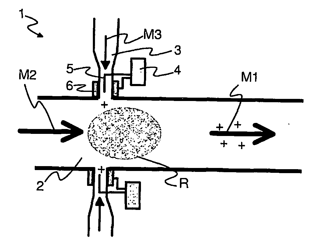
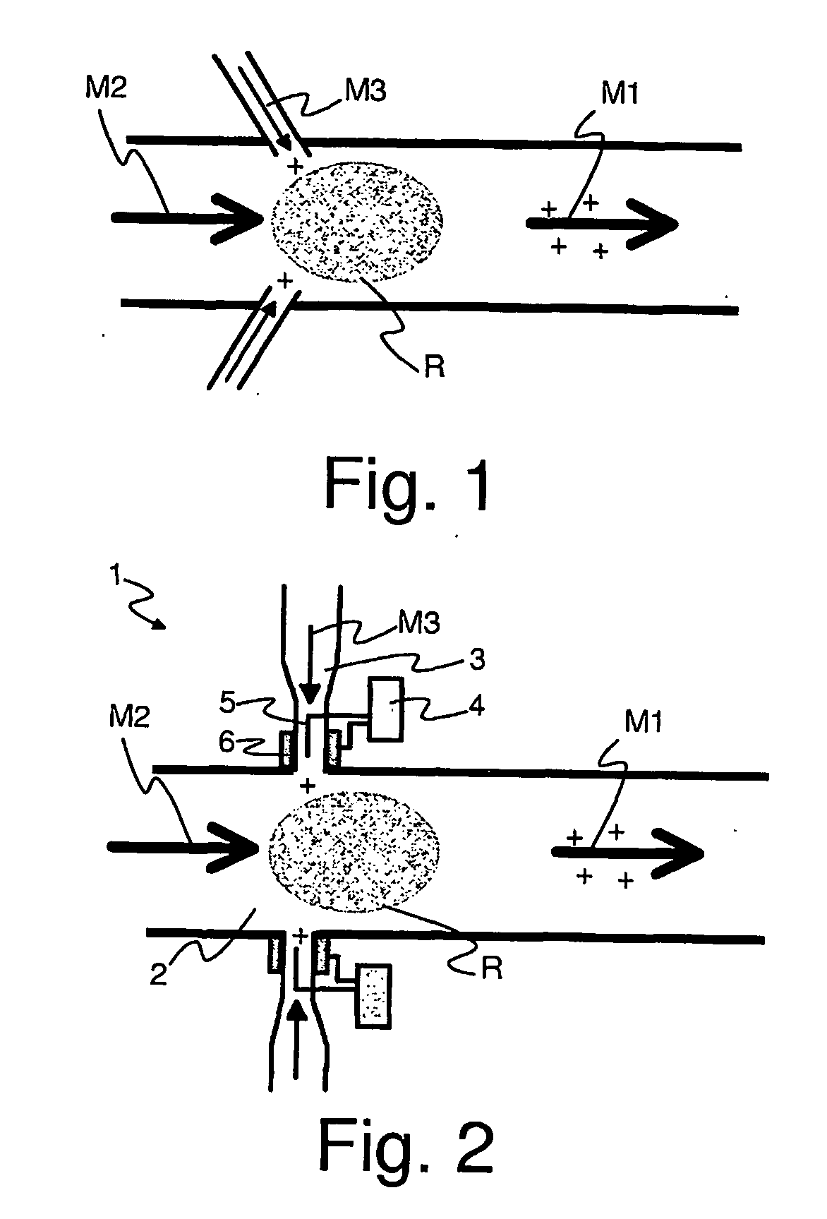
[0025] According to the invention, the electrical charge is introduced in the particle formation with the gas reacting with the reactant at that stage of the process in which the reactant is oxidized and the particles are formed. Advantageously the electrical charge is introduced in the process with oxidizing gas that reacts with the reactant, such as oxygen, air or carbon dioxide. The charge that can be either positive or negative is produced in the gas by means of a suitable charging method and device, which is preferably a corona charger, by means of which an even and efficient charge output is attained in the gas flow.

[0026]FIG. 1 shows, in principle, the formation of electrically charged particles M1 in accordance with the invention. In the example, particles M1 are formed of silicon tetrachloride M2 (SiCl4) and oxygen M3 (O2) in gaseous form, of which for example particles containing silicon oxide (SiO2) are formed. Typically several components are used in the process, wherei...


PUM

PropertyMeasurementUnit
Speedaaaaaaaaaa
Flow rateaaaaaaaaaa
Speedaaaaaaaaaa

Abstract

A method for charging particles used for processing of a material. At least a gaseous reactant is supplied and oxidizing gas is supplied to the reactant. The oxidizing gas is charged electrically before it is supplied to the reactant. The reactant and the oxidizing gas form charged particles. The material to be processed is advantageously a multicomponent oxide construction, such as an optical fiber preform. The invention also related to a charging device implementing the method.

Description

BACKGROUND OF THE INVENTION [0001] 1. Field of the Invention [0002] The invention relates to a method for charging particles, said particles being used for processing of an optical material, in which method at least a gaseous reactant is supplied and oxidizing gas is supplied to the reactant. The invention also relates to a particle charging device for forming particles, said particles being used for processing an optical material, which charging device comprises a channel for supplying a gaseous reactant, a channel for supplying oxidizing gas, and a charging member. [0003] 2. Description of the State of the Art [0004] An optical fiber is typically formed by drawing the fiber from a fiber preform in a fiber drawing tower. The properties of the finished fiber for their part are determined on the basis of the properties of the fiber preform used in the process of drawing the fiber. The properties of the fiber preform, in turn, are determined on the basis of the manufacturing method an...

Claims


Application Information

Patent Timeline
IPC IPC(8): C03B37/018C03C25/00C03B19/14C03B37/012C03C17/245
CPCC03B19/1415C03B37/0128C03B2207/81C03C17/245C03B2207/46C03B37/01807
Inventor JANKA, KAUKOFORSBLOM, TOMIRAJALA, MARKKU
Owner LIEKKI OY
Why Eureka
Try Eureka