Modular electronically reconfigurable battery system

a battery system and module technology, applied in the field of module electronic reconfigurable battery systems, can solve the problems of the most energy and power density of lithium-ion (li-ion) technology, and achieve the effect of simple scaling of more and easy configuration

Active Publication Date: 2007-03-22
L 3 APPLIED TECH
View PDF20 Cites 77 Cited by
  • Summary
  • Abstract
  • Description
  • Claims
  • Application Information

AI Technical Summary

Benefits of technology

[0012] According to embodiments of the present invention, the need for intermediate DC-DC power conversion circuitry is reduced or eliminated by using electronic switching to convert the battery pack modules from their normal parallel configuration for vehicle or ship load leveling and / or silent mobility functions, to a series configuration that is capable of delivering the necessary high power and high voltage output for short-term and pulsed load operations.
[0028] This more complex reconfigurable electrical energy storage system is especially useful in hybrid electric vehicles, ships, or boats (i.e., vehicles, ships, or boats powered by both a prime mover and an electrical energy power source) used in military operations and in other fixed or moving platforms where it is desirable to be able to redirect and level shift the stored energy in the reconfigurable electrical energy storage system to auxiliary higher voltage energy storage and deliver systems such as pulsed power weapon and protection systems. Examples of such reconfigurations include a shift from a low voltage parallel configuration to high voltage series / parallel configurations for optimizing impedance match, minimizing or eliminating the need for an associated power converter for pulsed power applications, powering other subsystems or matching variable DC link main systems as envisioned in, for instance, the original CHPS combat hybrid vehicle, which shifted from a 300-400V low voltage parade voltage to a higher 900-1200V combat status bus voltage.
[0033] Another embodiment employs a simple switching algorithm and a three switch and one diode configuration that guarantees no catastrophic battery or fire failures due to mistiming of the in high speed switching or modulating of the series connection switches in the intermediated switch array. This is accomplished by switching off or opening all of the positive and negative rail switches rail switches labeled P and N in simplified parallel operation diagram, then using just the one series switch connection labeled S and one Required steering diodes per module allows seamless high speed erecting and de-erecting of the batteries or capacitors in series or series voltage stepped VHV Output by selecting the number of series switches turned on or sequenced with no critical timing issues.
[0034] In another embodiment the base switch matrix can be effectively set to ‘ON’ at all times by replacing the switch matrix with hard wired parallel connections of the base voltage terminals of the ERB Arms. One notable improvement of this invention over the prior art is that it allows simple scaling of more by the simple addition of more modules without any rewiring due to its modular and scalar design. Sophisticated ERB systems with complete redundancy of the ERB star and multiple star configurations are easily configured by switched in and cross connected at the base and / or at the VHV level matrix levels.
[0035] In an alternative embodiment, VHV outputs can be steered in parallel operation through a simple VHV diode steering array. This allows complete or partial failure of one more ERB arms without rendering the system inoperative. Two sets of two arms each supply energy in parallel to the 10 Kv 150 kJ energy storage capacitor. As a result, the system can suffer a complete failure of one plus and one minus output ERB arm and still meet VHV mission requirements. Furthermore, the system can suffer the loss of three ERB arms before losing traction or moving capability. A multiple arms configuration, such as the “star” or “H”, is a great improvement over the single arm ERB configuration because parallel operation battery source resistance or ESR (Equivalent series resistance) is reduced by a factor of 4, or the number of arms in parallel.
[0037] In another embodiment nested ERB are used. Nested, or layered, ERB are ERB systems with nested or layered ERB are contained within each level of stackable modules. The next level of ERB is to use an ERB within the ERB module to reduce the base voltage and basic module voltage. An example is reducing a 720 volts ERB module to a lower voltage 36 volts ERB module using ten (10) sub ERB modules within each 720 volt ERB module. The advantage is it allows the Base voltage to be dropped and allows a finer resolution in the high voltage output example 10 sub modules×8 modules=80 voltage steps resolution in the VHV output. This allows the Base current in parallel operation to be teri times higher for high torque low speed application or to create long life parade ground low voltage power and shorter life high speed combat modes.

Problems solved by technology

Of these systems, the lithium-ion (Li-ion) technology is the most energy and power dense.

Method used


Image

  • Modular electronically reconfigurable battery system
  • Modular electronically reconfigurable battery system
  • Modular electronically reconfigurable battery system

Examples


example

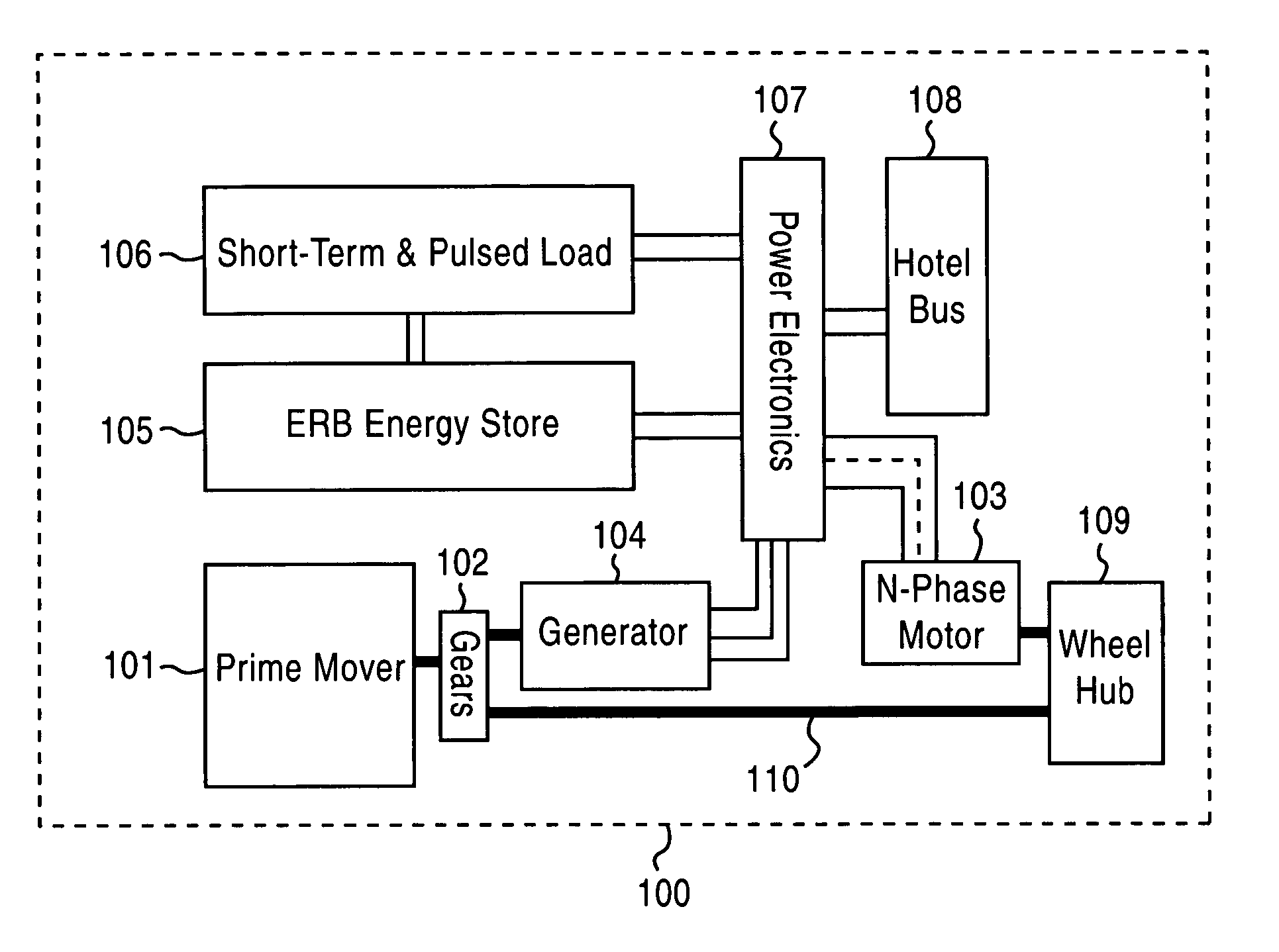
[0058] Assuming a 20-ton class vehicle and extrapolating from CHPS requirements, a conceptual design of an ERB for a hybrid electric vehicle with an EMA system has the following requirements: 1) Deliver up to 400 kW to the vehicle bus at 1 kV in parallel operation; 2) Recharge a 150-kJ capacitive store to 10 kV in 300 milliseconds; and 3) Support 30-45 minute silent operation at 80 kW. These requirements mandate the use of very high energy and power density batteries. Two candidate batteries are the HP series of lithium ion batteries being developed by SAFT and the lithium polymer batteries produced by Ultralife Batteries, Inc. for use in cell phones. The SAFT batteries have a slight advantage in usable power density and packaging for military use, whereas the Ultralife batteries have an advantage in cost (0.15-0.2 cents / J, 5-8 cents / Wpk, owing to volume production) and a potential for more compact packaging (prismatic) in ERB service.

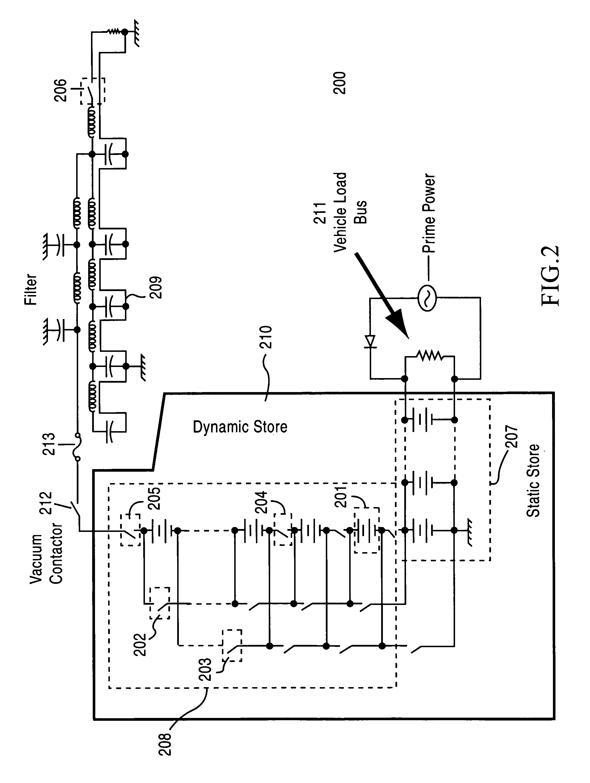
[0059] The ERB system in this case constitutes ...


PUM


Abstract

An electronically reconfigurable battery includes a number of battery modules selectively interconnected by a number of electronic switches, wherein a selectable number of battery modules may be connected either in a series configuration or in a parallel configuration, as a result of placing selected switches of said plurality of switches in open states or closed states. In a parallel configuration, the battery provides power to a primary load, such as a propulsion load for a vehicle. In a series configuration, the battery is configured to provide a high voltage and high power output to a short-term and / or pulsed load, such as an additional load provided on the vehicle. Current from the battery is limited in one of three ways: a) by the batteries themselves; b) a current limiting device or system in series with the total erected battery; or c) a single level power converter or current limiter that is used to erect and charge the capacitor bank in a sequential one level at a time manner until the battery is fully erected and the capacitor is fully charged.

Description

CROSS-REFERENCE TO RELATED APPLICATIONS [0001] This application claims priority to and is a continuation-in-part of U.S. patent application Ser. No. 10 / 631,017, filed on Jul. 31, 2003, the entire contents of which are incorporated herein by reference.BACKGROUND OF THE INVENTION [0002] 1. Field of the Invention [0003] The present invention relates to electrical energy storage systems and, in particular, to battery packs composed of multiple battery modules with adjustable configurations. [0004] 2. Description of the Related Art [0005] Hybrid electric vehicles (HEVs), hybrid electric ships and boats (such as the QE2) afford greater fuel efficiency than vehicles or vessels having only a prime mover (e.g., diesel or gasoline engine, gas turbine and fuel cell). Greater efficiency is obtained by using an energy store to level the load on the prime mover-providing peaking power to an electric motor, or storing energy during low power prime mover operation or during regenerative braking. [0...

Claims


Application Information

Patent Timeline
Patent Type & Authority Applications(United States)
IPC IPC(8): B60K6/00F41B6/00H02J7/00
CPCF41B6/00Y02T10/7055H02J7/0024Y02T10/70Y02P70/50
Inventor WEIDENHEIMER, DOUGLAS M.DONEGAN, KEVIN J.MORTON, DAVID WAYNE
Owner L 3 APPLIED TECH
Why Eureka
Try Eureka