
Molding system and method

a molding system and metal wall technology, applied in the field of material processing, can solve the problems of hot metal wall and tacky surface of powder particles, and achieve the effect of high heat transfer ra

Inactive Publication Date: 2007-03-22
NEW HEAT
View PDF10 Cites 21 Cited by
  • Summary
  • Abstract
  • Description
  • Claims
  • Application Information

AI Technical Summary

Benefits of technology

[0007] In a broad sense, the invention involves the provision of an electrothermic material layer arranged to contact a material being processed with heat transfer from the electrothermic layer or to contact an intermediate layer or layers of which one is in direct contact with the material being heat processed with heat transfer from the electrothermic layer, the electrothermic layer or the intermediate one layer being capable of assisting to shape or maintaining the shape of the material being so processed. The electrothermic layer is advantageously arranged to substantially envelop the material being processed or at least arranged to be substantially co-extensive with a large portion of the surface of the material being processed whereby the conductive heat transfer area is relatively large, being preferably at least about ⅓, and more preferably at least about ½, and most preferably at least about ¾, of the surface being shaped or maintained of a side of the material being processed, so as to promote a high rate of heat transfer between the electrothermic layer and the material being processed.

Problems solved by technology

When the mold rotates in the oven, the mold's metal wall becomes hot and the surface of the powder particles becomes tacky.

Method used


Image

  • Molding system and method
  • Molding system and method
  • Molding system and method

Examples


Embodiment Construction

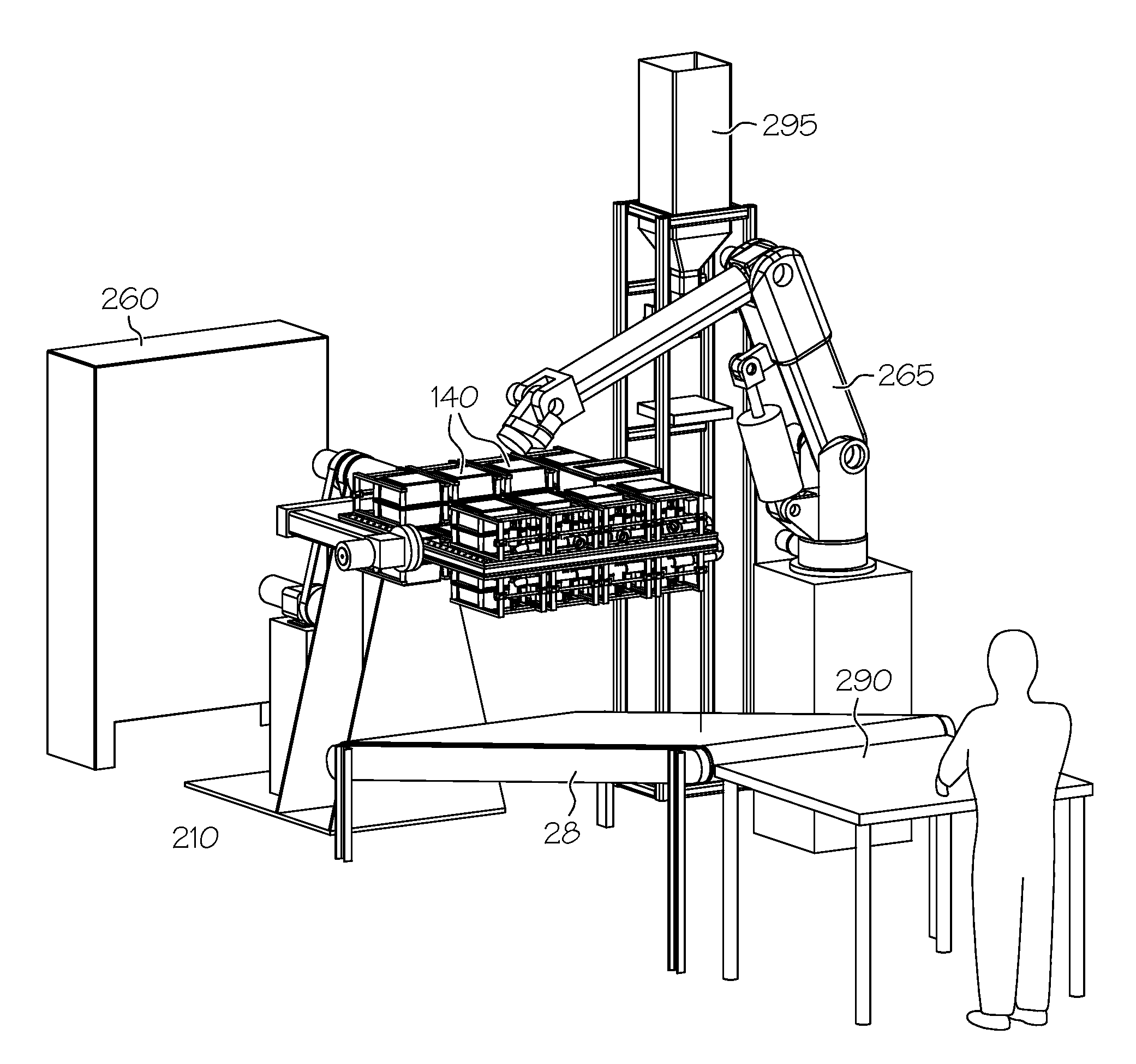
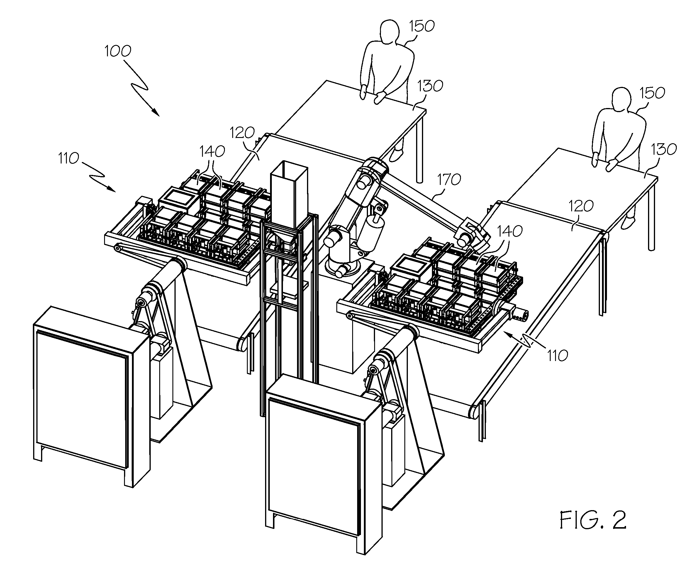
[0021] The present invention provides systems and methods for processing material being heated and shaped such as occurs in rotational molding. The present invention will now be described with reference to the drawings, wherein like reference numerals are used to refer to like elements throughout. It is to be appreciated that the various drawings are not necessarily drawn to scale from one figure to another nor inside a given figure, and in particular that the size of the components are arbitrarily drawn for facilitating the reading of the drawings. In the following description, for purposes of explanation, numerous specific details are set forth in order to provide a thorough understanding of the present invention. It should be evident, however, that the present invention may be practiced without these specific details.

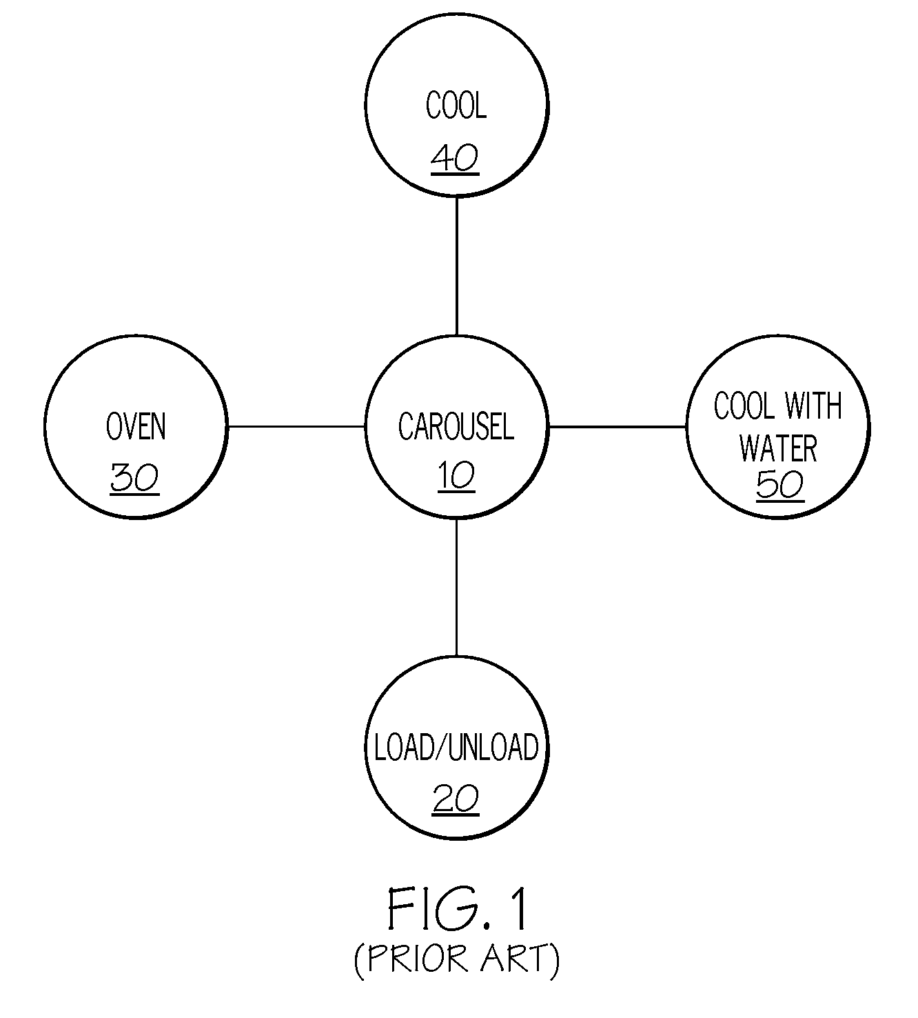
[0022] Referring initially to FIG. 1, a conventional rotational molding, or rotomolding, system is illustrated. The conventional system includes a carousel 10 havin...


PUM

PropertyMeasurementUnit
timeaaaaaaaaaa
timeaaaaaaaaaa
shapeaaaaaaaaaa

Abstract

A molding system includes a single molding machine, or station, having one or more molds therein, wherein the single machine, or station, is operable to both heat and cool the material present within the one or more molds while rotating the mold. The single machine, or station, can also be loaded with starting material and unloaded directly at the machine.

Description

FIELD OF THE INVENTION [0001] The present invention relates to material processing, and more particularly, to systems and methods for molding plastics and other materials with heat. BACKGROUND OF THE INVENTION [0002] One particular type of molding, rotational molding, also referred to as rotomolding, is a widely used process to produce hollow articles such as toys, sporting equipment, containers, water tanks, etc. The rotomolding process includes introducing a known amount of plastic in powder form into a hollow, shell-like mold. The mold is rotated about two or more principal axes at relatively low speeds as it is heated in an oven so that the plastic enclosed in the mold adheres to and forms a monolithic layer against the mold surface. When the mold rotates in the oven, the mold's metal wall becomes hot and the surface of the powder particles becomes tacky. The particles stick to the mold wall and to each other, thus building up a loose powdery mass against the mold wall. A major ...

Claims


Application Information

Patent Timeline
Patent Type & Authority Applications(United States)
IPC IPC(8): B27N3/00
CPCB29C33/02B29C41/46B29C41/06
Inventor STEINBERGER, DAVIDYERIAN, DIRK N.
Owner NEW HEAT
Learn More