Direct mode pulse width modulation for DC to DC converters

a dc converter and direct mode technology, applied in the direction of dc-dc conversion, power conversion systems, climate sustainability, etc., can solve the problems of slow response to load transients, inability to parallel operation of voltage mode pwm converters b>100/b>, and high cost of discrete sensing resistors, etc., to achieve fast transient response, inherently stable, and simple control circuit

Inactive Publication Date: 2007-03-22
AMAZION ELECTRONICS
View PDF9 Cites 93 Cited by
  • Summary
  • Abstract
  • Description
  • Claims
  • Application Information

AI Technical Summary

Benefits of technology

[0016] It is therefore an aspect of the present invention to provide a DC to DC converter, which has a simple control circuit, is inherently stable, and is of fast transient response.

Problems solved by technology

Major disadvantage of voltage mode is its slow response to load transients, owing to the compensation needed on error amplifier 102 to stabilize the control loop.
And due to the lack of inductor current information, the voltage mode PWM converter 100 is not suitable for parallel operation.
A discrete sensing resistor is expensive and introduces additional conduction loss.
In many cases, because of the device parameter spread (such as Rds) and the current-sense amplifier input offset voltage, the extraction of inductor current information is significantly inaccurate.
Moreover, its compensation network, although simpler than that of the voltage mode PWM converter 100, still demands careful and elaborate design.
In addition, for a multi-phase (parallel operation) design, each converter needs a separate current sensor, causing proportionally higher implementation cost.
However, the switching frequency of the ripple mode converter is not constant.
Moreover, if its output capacitor has a low ESR, the ripple of the output voltage (Vout) is very small, it will lead to jittery switching frequency.
Consequently, ripple mode converters are generally considered as not suitable for multi-phase applications difficult.

Method used


Image

  • Direct mode pulse width modulation for DC to DC converters
  • Direct mode pulse width modulation for DC to DC converters
  • Direct mode pulse width modulation for DC to DC converters

Examples


Embodiment Construction

[0034] Reference will now be made in detail to the preferred embodiments of the present invention, examples of which are illustrated in the accompanying drawings. Wherever possible, the same reference numbers are used in the drawings and the description to refer to the same or like parts.

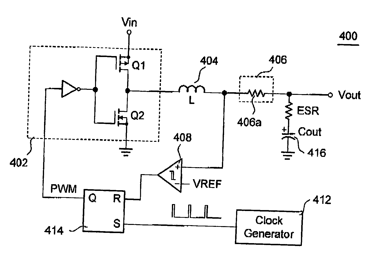
[0035] The present invention feeds back the output voltage (Vout) by a voltage sensor, which contains the information of the output voltage (Vout) as well as the inductor DC current. The DC to DC converter of the present invention has a constant switching frequency and supports a low ESR output capacitor. The control circuit of the DC to DC converter is simple, inherently stable, and has fast transient response. Furthermore, the DC to DC converter has inherent current-sharing characteristics, ideal for multi-phase applications, such as several converters operating in parallel.

[0036]FIG. 4A is a circuit diagram of one preferred embodiment of the present invention, and FIG. 4B is a graph illustratin...


PUM


Abstract

A DC to DC converter has an inverter, an inductor, a voltage sensor, a comparator, a clock generator, a driver and an output capacitor. The inverter converts an input voltage into a square-wave voltage. The inductor is electrically connected to an output of the inverter. The voltage sensor is electrically connected to the inductor and derives a sense voltage. The comparator compares the sense voltage and a reference voltage. The clock generator generates a reference clock pulse. The driver is triggered by the reference clock pulse and switches the inverter according to an output of the comparator. The output capacitor is electrically connected between the voltage sensor and the ground.

Description

BACKGROUND [0001] 1. Field of Invention [0002] The present invention relates to the DC to DC converters. More particularly, the present invention relates to pulse width modulation (PWM) DC to DC converters. [0003] 2. Description of Related Art [0004] DC to DC converters are well known in the field of electronics. Such circuitry or devices are typically employed to convert from one DC voltage level to another DC voltage level. They are used in a variety of environments. For instance, several kinds of such converters are used to supply microprocessor core voltage. One kind of such converters is referred to as a fixed frequency converter, also known as a pulse-width modulated (PWM) converter. PWM converters include voltage mode converters and current mode converters. [0005]FIG. 1A is a circuit diagram of a voltage mode PWM converter; and FIG. 1B is a graph illustrating PWM timing and waveforms of the converter illustrated in FIG. 1A. The following description is made with reference to ...

Claims


Application Information

Patent Timeline
Patent Type & Authority Applications(United States)
IPC IPC(8): G05F1/00
CPCY02B70/1466H02M3/1588Y02B70/10
Inventor LIU, KWANG-HWA
Owner AMAZION ELECTRONICS
Why Eureka
Try Eureka