
Detail-in-context lenses for online maps

a technology of detail in context and online map, which is applied in the field of computer graphics processing, can solve the problems of inability to effectively display detailed information for selected graphic objects, loss of relative location of objects user loss of sight of the context within which objects are positioned in the larger image, so as to improve the legibility of at least one text label

Inactive Publication Date: 2007-03-22
INTELLECTUAL VENTURES ASSETS 186 LLC +1
View PDF34 Cites 112 Cited by
  • Summary
  • Abstract
  • Description
  • Claims
  • Application Information

AI Technical Summary

Benefits of technology

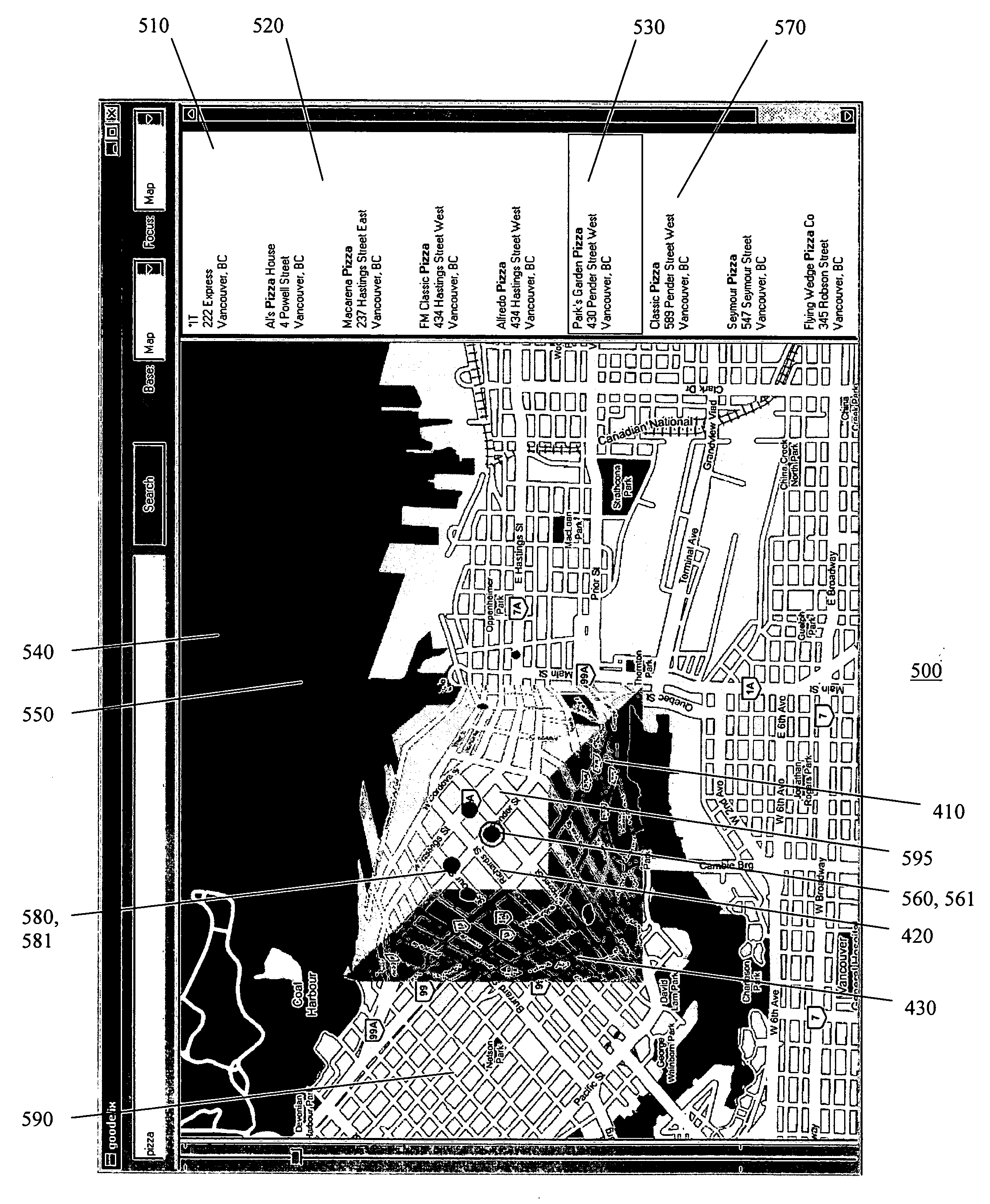
[0010] The method may further include displaying the presentation on the display screen. The method may further include inserting an icon into the presentation at the location to highlight the location. The original map image may be an online map image. The presentation may be displayed in a first window on the display screen and the search results may be displayed in a second window on the display screen. The original map image may include one or more text labels and the method may further include relocating at least one text label appearing within the lens to within the focal region of the lens to improve legibility of the at least one text label. The method may further include adjusting a font size of the at least one text label within the focal region to improve legibility of the at least one text label. The signal may be received from a pointing device manipulated by a user. The signal may be generated from a ranking of the search results. The method may further include inserting information pertaining to the search result into the presentation within the lens. The information may be one or more of a text message, a telephone number, an email address, an advertisement, and a street address. The method may further include receiving one or more signals to adjust at least one of a size, a shape, and the magnification of the focal region. The method may further include receiving the one or more signals through a graphical user interface (“GUI”) displayed over the lens. The GUI may have means for adjusting at least one of the size, shape, and magnification of the focal region. At least some of the means may be icons. The means for adjusting the size and shape may be at least one handle icon positioned on a perimeter of the focal region. The means for adjusting the magnification may be a slide bar icon. The method may further include receiving one or more signals through a GUI displayed over the lens to adjust at least one of a size and a shape of the shoulder region, wherein the GUI has one or more handle icons positioned on a perimeter of the shoulder region for adjusting at least one of the size and the shape of the shoulder region. The step of applying may further include displacing the original image onto the lens to produce a displacement and perspectively projecting the displacement onto a plane in a direction aligned with a viewpoint for the region-of-interest. And, the search results may be generated by an online search engine.

Problems solved by technology

One problem with these computer graphics systems is their inability to effectively display detailed information for selected graphic objects when those objects are in the context of a larger image.
While an application may provide a GUI for a user to access and view detailed information for a selected object in a larger image, in doing so, the relative location of the object in the larger image may be lost to the user.
Thus, while the user may have gained access to the detailed information required to interact with the object, the user may lose sight of the context within which that object is positioned in the larger image.
The interaction may further distract the user from the context in which the detailed information is to be understood.

Method used


Image

  • Detail-in-context lenses for online maps
  • Detail-in-context lenses for online maps
  • Detail-in-context lenses for online maps

Examples


Embodiment Construction

[0024] In the following description, details are set forth to provide an understanding of the invention. In some instances, certain software, circuits, structures and methods have not been described or shown in detail in order not to obscure the invention. The term “data processing system” is used herein to refer to any machine for processing data, including the computer systems and network arrangements described herein. The present invention may be implemented in any computer programming language provided that the operating system of the data processing system provides the facilities that may support the requirements of the present invention. Any limitations presented would be a result of a particular type of operating system or computer programming language and would not be a limitation of the present invention.

[0025] The “screen real estate problem” generally arises whenever large amounts of information are to be displayed on a display screen of limited size. Known tools to addr...


PUM


Abstract

A method for providing a presentation of a region-of-interest within an original image to a client, the original image being stored in a content server coupled to a proxy server and the client over a network, the method comprising: in response to a request from the client for the presentation, receiving at the proxy server the original image from the content server; applying a lens to the original image to produce the presentation at the proxy server, the lens having a focal region with a magnification for the region-of-interest at least partially surrounded by a shoulder region where the magnification diminishes; and, sending the presentation to the client. In addition, a method for generating a presentation of search results pertaining to a geographic area for display on a display screen, comprising: receiving a signal selecting a search result from the search results, the search result having a location within the geographic area; and, applying a lens to an original map image for the geographic area to produce the presentation, the lens having a focal region with a magnification for the location at least partially surrounded by a shoulder region where the magnification diminishes. Furthermore, a method for generating a presentation of a path from a first location to a second location in a geographic area for display on a display screen, comprising: displaying an original map image for the geographic area having an overlaid representation of the path; receiving a signal selecting a location on the original map image, wherein the location is limited to at least one of being on the representation of the path and being within a predetermined distance from the representation of the path; and, applying a lens to the original map image to produce the presentation, the lens having a focal region with a magnification for the location at least partially surrounded by a shoulder region where the magnification diminishes.

Description

[0001] This application claims priority from U.S. Provisional Patent Application No. 60 / 693,411, filed Jun. 24, 2005, and incorporated herein by reference.FIELD OF THE INVENTION [0002] This invention relates to the field of computer graphics processing, and more specifically, to a method and system for applying detail-in-context lenses to online maps and mapping applications. BACKGROUND OF THE INVENTION [0003] Modern computer graphics systems, including virtual environment systems, are used for numerous applications such as online digital mapping, navigation, surveillance, and even playing computer games. In general, these applications are launched by the computer graphics system's operating system upon selection by a user from a menu or other graphical user interface (“GUI”). A GUI is used to convey information to and receive commands from users and generally includes a variety of GUI objects or controls, including icons, toolbars, drop-down menus, text, dialog boxes, buttons, and ...

Claims


Application Information

Patent Timeline
Patent Type & Authority Applications(United States)
IPC IPC(8): G09G5/00
CPCG06F3/0481G06F2203/04805G09B29/10G09B29/007G06Q30/02
Inventor SHOEMAKER, GARTH B.D.BAAR, DAVID J.P.
Owner INTELLECTUAL VENTURES ASSETS 186 LLC
Learn More