Method of adjusting the resonant frequency of an assembled torsional hinged device

Inactive Publication Date: 2007-03-22
TEXAS INSTR INC
View PDF4 Cites 22 Cited by
  • Summary
  • Abstract
  • Description
  • Claims
  • Application Information

AI Technical Summary

Benefits of technology

[0005] These and other problems are generally solved or circumvented and technical advantages are generally achieved by embodiments of the present invention, which provides a method of adjusting the resonant frequency of an assembled torsional hinged structure (such as a mirror). The method comprises the step of mounting the torsional hinged device to a support structure, and providing a drive mechanism proximate the mounted torsional hinged device to oscillate

Problems solved by technology

However, every new technology has its own set of problems and using torsional hinged mirrors in precision applications is no exception.
One problem area is the manufacturing of such torsional hinged mirrors with a specific resonant frequency.
Unfortunately, each of the assembled mirrors will not have the same resonant frequency because of variations in the silicon processing, silicon wafer thickness, and the exact mass distribution of the composite structure including the magnet size and density as well as variations in adhesive bond lines.

Method used


Image

  • Method of adjusting the resonant frequency of an assembled torsional hinged device
  • Method of adjusting the resonant frequency of an assembled torsional hinged device
  • Method of adjusting the resonant frequency of an assembled torsional hinged device

Examples


Embodiment Construction

[0011] The making and using of the presently preferred embodiments are discussed in detail below. It should be appreciated, however, that the present invention provides many applicable inventive concepts that can be embodied in a wide variety of specific contexts. The specific embodiments discussed are merely illustrative of specific ways to make and use the invention, and do not limit the scope of the invention.

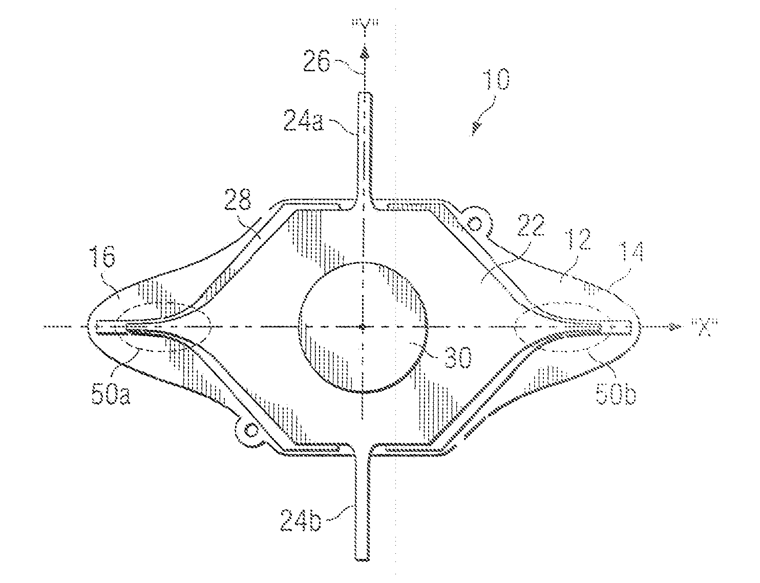
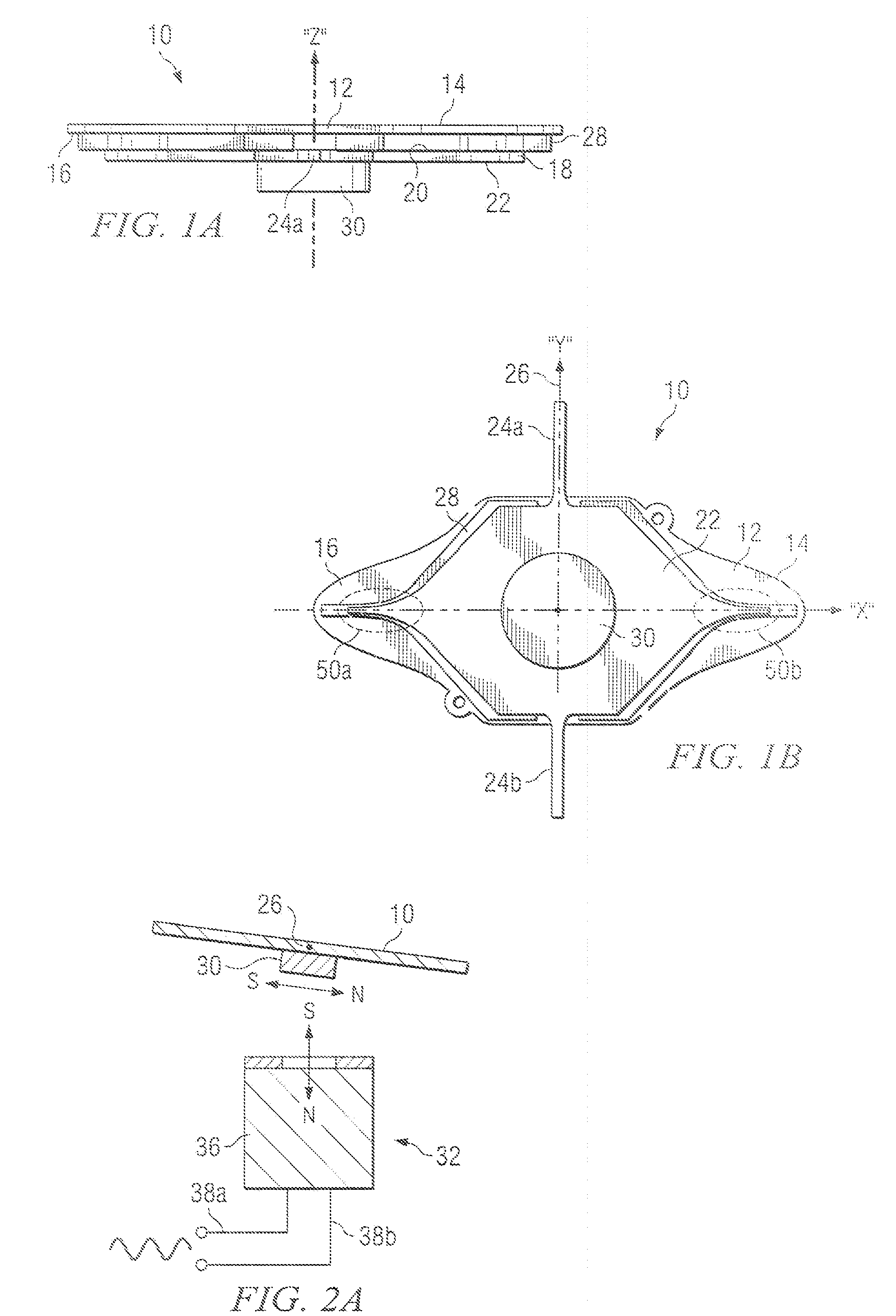
[0012] Referring now to FIGS. 1A and 1B, there is shown a side view and a bottom view of a multilayer torsional hinged resonant device incorporating the teachings of the present invention. As shown, the assembly 10 includes a front layer 12 having a top surface 14 (such as a reflective or mirror surface) and a back surface 16. Also included is a hinge layer 18 having a front portion 20 and a magnet side 22. Hinge layer 18 also defines a pair of torsional hinges 24a and 24b that are attached to a support structure (not shown) for supporting the torsional hinged device 10. As...


PUM


Abstract

A method of adjusting the resonant frequency of a torsional hinged device such as a resonant mirror is disclosed. A material such as printer ink, epoxy, or solder balls is applied to the tips of the torsional hinged device to lower the frequency into a selected frequency range.

Description

TECHNICAL FIELD [0001] The present invention relates to resonant torsional hinged mirrors and more particularly to the adjusting of the mirror resonant frequency after assembly of the mirror. BACKGROUND [0002] In recent years, MEMS (Micro Electro Mechanical Systems) torsional hinged mirror structures have made significant strides as replacements for spinning polygon mirrors used as the engine for high speed printers and some types of display systems. Such torsional hinged mirror structures have certain advantages over the spinning polygon mirrors including lower cost and weight. However, every new technology has its own set of problems and using torsional hinged mirrors in precision applications is no exception. [0003] One problem area is the manufacturing of such torsional hinged mirrors with a specific resonant frequency. The silicon components used to fabricate such torsional hinged mirrors may be manufactured from silicon wafers using semiconductor manufacturing process steps an...

Claims


Application Information

Patent Timeline
IPC IPC(8): G02B26/08
CPCG02B26/085B81C1/0065
Inventor TURNER, ARTHUR MONROEDEWA, ANDREW STEVENORCUTT, JOHN W.HEATON, MARK W.
Owner TEXAS INSTR INC
Why Eureka
Try Eureka