Optical transmitting apparatus and optical communication system

a technology of optical communication system and optical transmission apparatus, which is applied in the direction of optics, electromagnetic transceivers, instruments, etc., can solve the problems that the amount of phase shift may sometimes deviate from the prescribed value, and achieve the effect of constantly avoiding deterioration of communication quality

Active Publication Date: 2007-03-22
FUJITSU LTD
View PDF35 Cites 61 Cited by
  • Summary
  • Abstract
  • Description
  • Claims
  • Application Information

AI Technical Summary

Benefits of technology

[0014] In the above optical transmitting apparatus, if the amount of phase shift in the phase shift unit is appropriately set, a frequency component, which is twice of the frequency of the low-frequency signal, is comprised in the modulated optical signal. Therefore, by monitoring that frequency component, the amount of phase shift can be appropriately adjusted. On the other hand, when the amount of phase shift deviates from the appropriate value, a frequency component of the low-frequency signal is comprised in the modulated optical signal. At that time, a phase of the low-frequency signal detected from the modulated optical signal when the amount of phase shift deviates in a positive direction, is inverted from a phase of the low-frequency signal detected from the modulated optical signal when the amount of phase shift deviates in a negative direction. Therefore, by monitoring the phase of the low-frequency signal, the amount of phase shift can be appropriately adjusted.
[0015] According to the present invention, the amount of phase shift of a phase shifter element in a phase modulator comprised in the optical transmitting apparatus is appropriately adjusted, therefore, deterioration of communication quality can be avoided. Particularly, when deviation of the amount of phase shift occurs due to thermal change, aged degradation etc., the amount of phase shift is dynamically adjusted appropriately, thus it is possible to constantly avoid the deterioration of communication quality.

Problems solved by technology

However, the amount of phase shift may sometimes deviate from a prescribed value due to thermal change and aged degradation etc.

Method used


Image

  • Optical transmitting apparatus and optical communication system
  • Optical transmitting apparatus and optical communication system
  • Optical transmitting apparatus and optical communication system

Examples


first embodiment

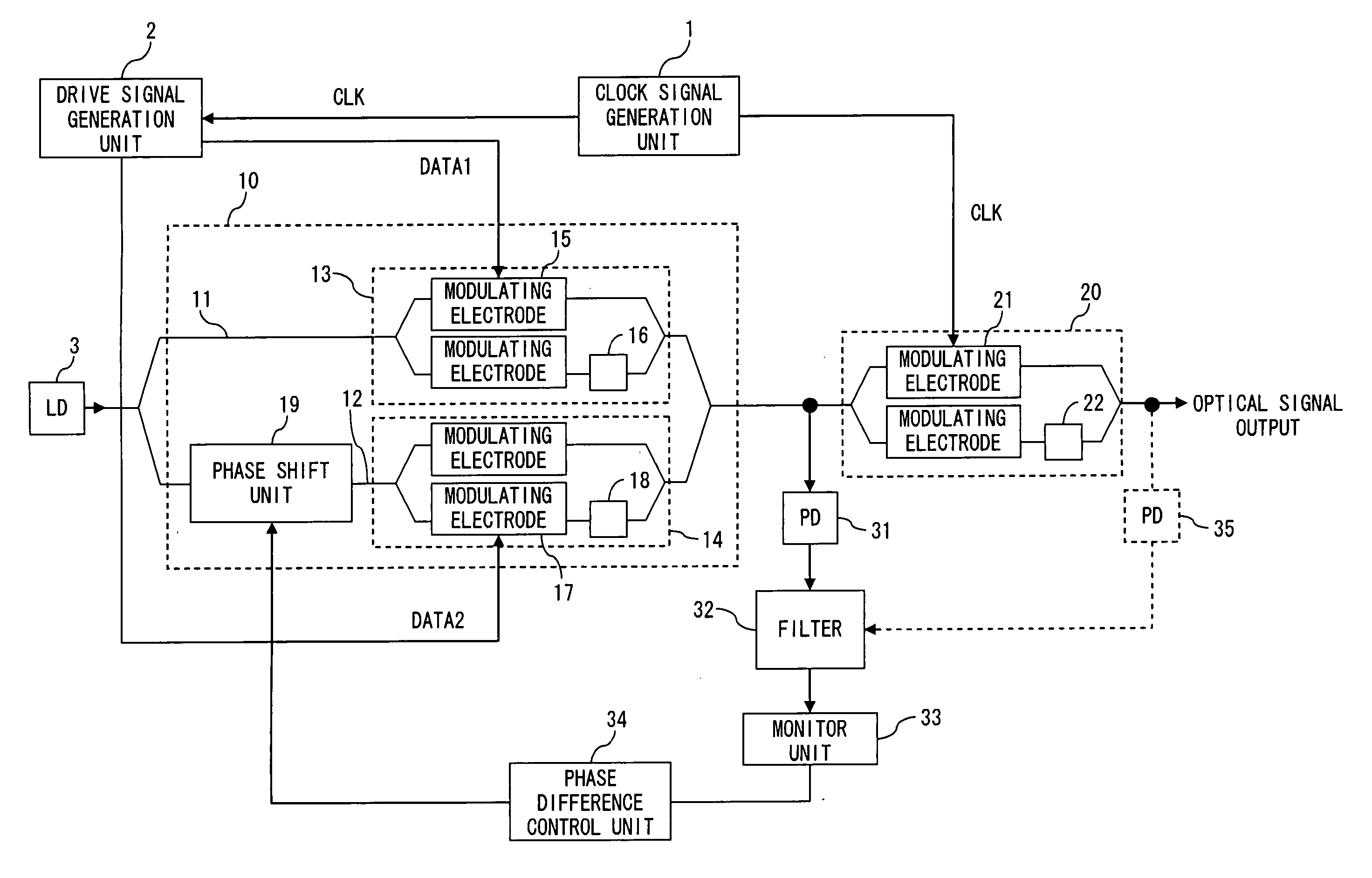
[0045]FIG. 5 is a diagram describing a configuration of the optical transmitting apparatus of the first embodiment of the present invention. This optical transmitting apparatus generates and transmits a DQPSK optical signal in the following description.

[0046] In FIG. 5, a clock signal generation unit 1 generates a clock signal. The frequency of the clock signal is, for example, a symbol frequency. In this case, if the bit rate of the transmitted data is 43 Gbps, the symbol frequency is 21.5 GHz. A drive signal generation unit 2 generates data signals DATA1 and DATA2 for generating a modulated optical signal. Here, the data signals DATA1 and DATA2 can be obtained by encoding the transmission data using a DQPSK pre-coder. An optical source (LD) 3 is a semiconductor laser, for example, and generates an optical CW. The wavelength of the optical CW is not limited in particular; however, 1550 nm band is used for example.

[0047] A data modulator unit 10 generates a DQPSK optical signal by...

second embodiment

[0062]FIG. 11 is a diagram showing a first configuration of an optical transmitting apparatus of the second embodiment of the present invention. In the optical transmitting apparatus of the second embodiment, the amount of phase shift is adjusted using a low-frequency signal. Numerical references shared in FIG. 5 and FIG. 11 indicate the same elements.

[0063] A low-frequency oscillator 41 generates a low-frequency signal with several kHz through several MHz. In the following description, the frequency of the low-frequency signal is referred to as “f0”. The low-frequency signal is a sinusoidal signal or rectangular wave signal, for example, and its amplitude is so small as not to give adverse effect on optical signals to be transmitted. The low-frequency signal is fed to the phase shift unit 19 via a low-frequency superimposing unit 42. For that reason, the amount of phase shift in the phase shift unit 19 changes (or dithers) on a periodic basis in accordance with the voltage of the ...

third embodiment

[0095]FIG. 28 is a diagram showing a first configuration of the optical transmitting apparatus of the third embodiment of the present invention. FIG. 29 is a diagram showing a second configuration of the optical transmitting apparatus of the third embodiment of the present invention. The numerical references in common among FIG. 5, FIG. 28 and FIG. 29 indicate the same elements. Either of the photodetector 31 or the photodetector 35 can be used as a photodetector.

[0096] In FIG. 28, a DC component removal element 51 is, for example, a condenser, and removes the DC component from the output signal of the filter 32. A mixer 52 squares the output signal of the DC component removal element 51. Here, the mixer circuit 52 is not limited in particular; however, is realized by an analog multiplier circuit comprising a Gilbert cell, for example. In such a case, a squared signal is obtained by multiplying the output signal of the DC component removal element 51 by itself using the analog mult...


PUM


Abstract

A data modulator unit generates a DQPSK optical signal in accordance with a data signal. A phase shift unit provides a phase difference of π/2 between a pair of arms. A photodetector converts an output signal of the data modulator unit into an electrical signal. A filter is a low-pass filter with a cut-off frequency lower than a symbol frequency, and filters an output signal of the photodetector. A monitor unit detects power of an output signal of the filter. A phase difference control unit adjusts the amount of phase shift in the phase shift unit so as to minimize power of an output signal of the filter.

Description

BACKGROUND OF THE INVENTION [0001] 1. Field of the Invention [0002] The present invention relates to an optical transmitting apparatus and an optical communication system, and in particular, relates to optical transmitting apparatus for transmitting an optical signal using PSK modulation and an optical communication system comprising such optical transmitting apparatus. [0003] 2. Description of the Related Art [0004] Development of a practical implementation of an optical transmitting apparatus aiming to establish a high capacity and long distance optical transmission system has been awaited in recent years. Particularly, expectations for implementation of an optical transmitting apparatus, which employs an optical modulation technique adequate for high capacity and long-distance, to an actual system are growing high. In order to meet with expectations, optical transmission systems using phase shift keying such as DPSK (Differential Phase Shift Keying) and DQPSK (Differential Quadra...

Claims


Application Information

Patent Timeline
Patent Type & Authority Applications(United States)
IPC IPC(8): H04B10/04H04B10/40H04B10/07H04B10/50H04B10/516H04B10/548H04B10/60H04B10/61
CPCG02F1/0123G02F1/2255H04B10/505H04B10/5051H04B10/58H04B10/50575H04B10/50577H04B10/50597H04B10/5053
Inventor MIURA, AKIRANAKAMURA, KENTAROONAKA, HIROSHIAKIYAMA, YUICHIOOI, HIROKIRASMUSSEN, JENSHOSHIDA, TAKESHI
Owner FUJITSU LTD
Why Eureka
Try Eureka