Application of microsystems for real time IEQ control

a microsystem and real-time ieq technology, applied in the field of indoor environmental control, can solve the problems of inability to provide any granular measurement of indoor environmental quality, no reliable or comprehensive way to quantify or measure the indoor environmental quality of a building, and the solution is either not cost-effective, or at least not if implemented

Active Publication Date: 2007-03-22
SIEMENS IND INC
View PDF16 Cites 36 Cited by
  • Summary
  • Abstract
  • Description
  • Claims
  • Application Information

AI Technical Summary

Benefits of technology

[0008] The present invention addresses the above described needs, as well as others, by employing wireless MEMS microsystem which are configured to measure a plurality of parameters relating to IEQ, and communicate these parameters, preferably wirelessly, to data processing equipment. The use of MEMs in sufficient quantities for this purpose makes possible real-time IEQ monitoring and / or control.
[0010] In other embodiments, some or all of the microsystems need not be wireless. However, there is an advantage to the use of wireless microsystems because it reduces labor and material costs associated with running wires.

Problems solved by technology

While the importance of environmental quality has been realized, to date there has been no reliable or comprehensive way to quantify or measure the indoor environmental quality of a building.
Temperatures can be maintained, and light fixtures kept operational, but these alone cannot provide any granular measurement of indoor environmental quality (IEQ).
Thus, although the building industry has experienced a tremendous interest in the subject due to proven research that links IEQ to health and productivity, the scope of IEQ measurement remains within the bounds of spot-checking of conditions, intermediate sampling of conditions using portable data logging computers, and some limited monitoring of some parameters.
These solutions are either not cost effective, or at least would not be if implemented to the extent necessary to generate comprehensive monitoring.

Method used


Image

  • Application of microsystems for real time IEQ control
  • Application of microsystems for real time IEQ control
  • Application of microsystems for real time IEQ control

Examples


Embodiment Construction

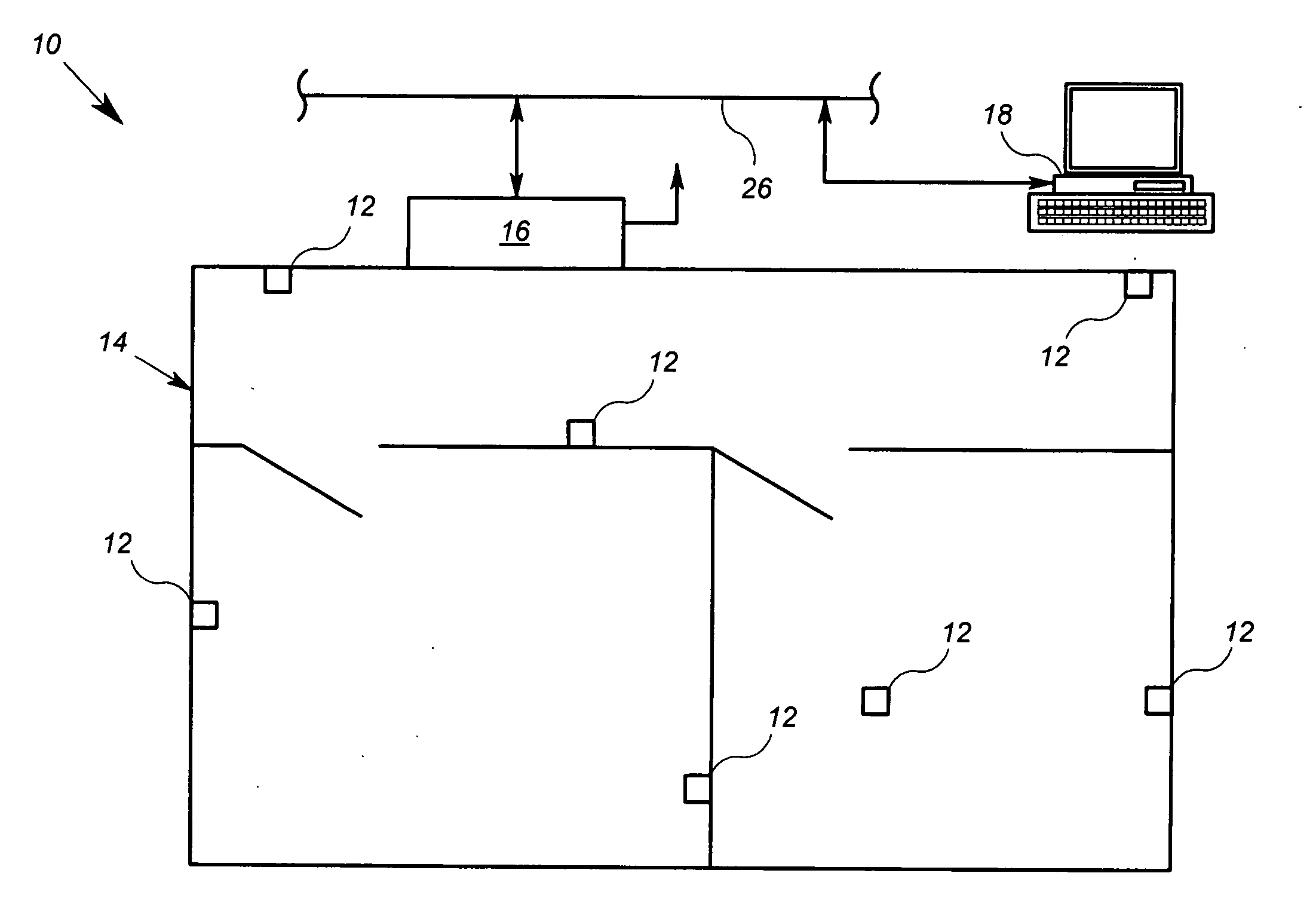
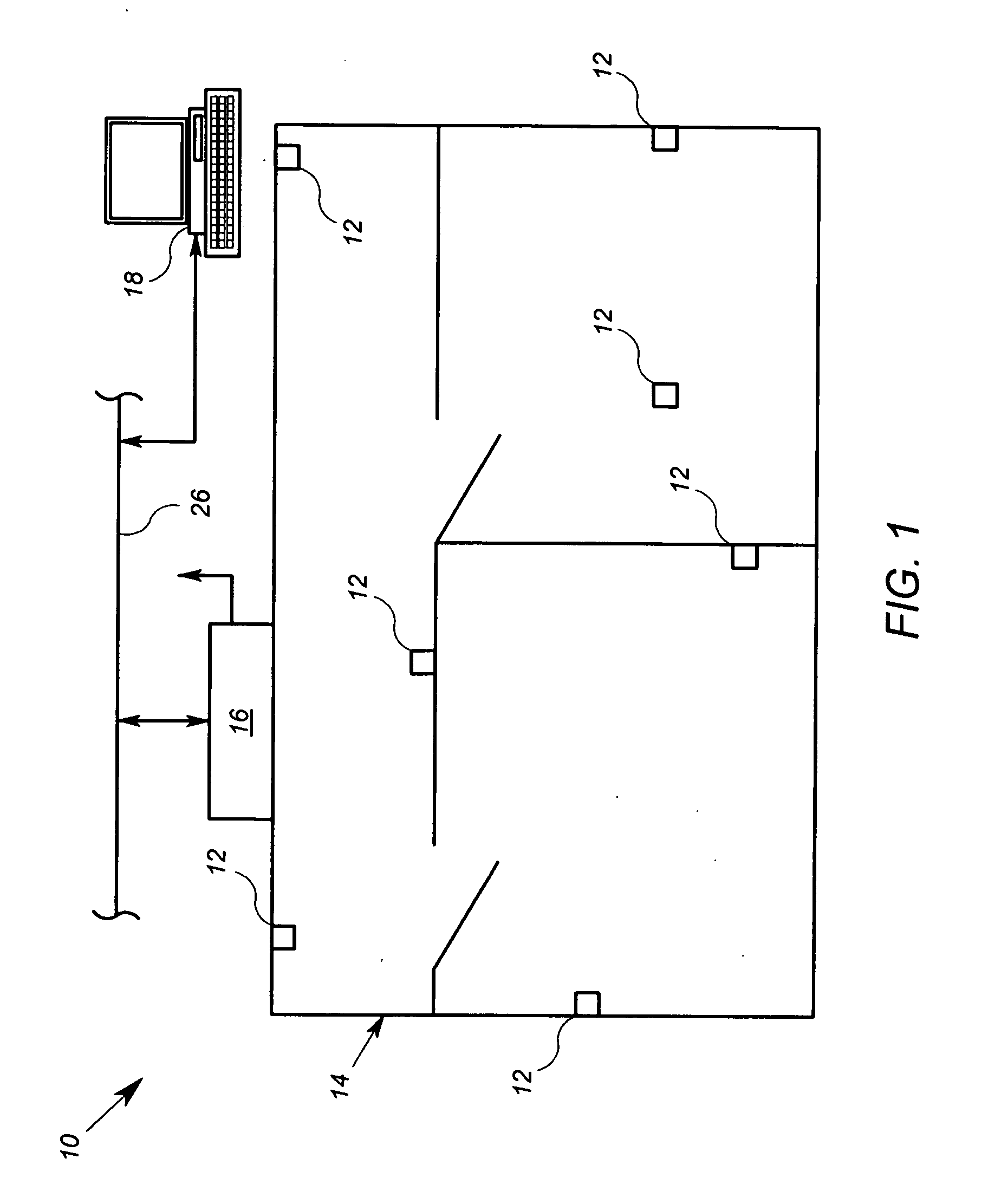
[0018]FIG. 1 shows an arrangement 10 that includes a plurality of wireless Microsystems 12, each microsystem 12 is operable to measure a plurality of IEQ related parameters in a building environment 14 and is further operable to communicate the parameters wirelessly to a network device 16. The network device 16 is operable to communicate the parameters of the plurality of microsystems 12 to a central data processor 18 that is able to generate a metric of the IEQ based on the parameters, and to update the metric in an ongoing basis.

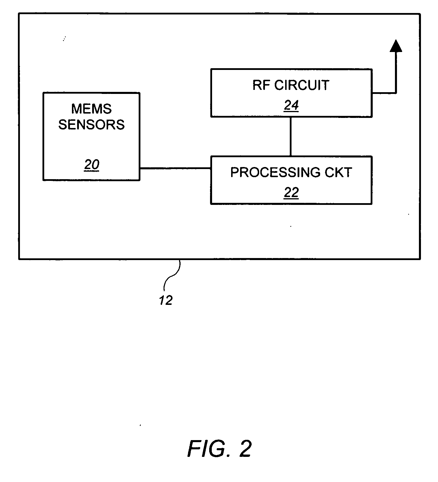
[0019] Referring to FIG. 2, the current state of the art of microsystems is sufficient to create a microsystem operable to measure and / or monitor IEQ parameters such as total volatile organic compounds (TVOC), temperature, mean radiant temperature, air flow rate, CO, CO2, relative humidity, light level, and even sound. Each microsystem 12 may therefore employ MEMS sensors 20 that measure some or all of these values. The microsystem 12 may also incorporate...


PUM


Abstract

An arrangement includes a plurality of wireless microsystems and a central data processor. Each microsystem is operable to measure a plurality of indoor environmental quality-related parameters and is operable to communicate first information pertaining to the measured parameters wirelessly to a network device. The central data processor is operably coupled to receive the first information from the network device, and further configured to generate a metric value of an indoor environmental quality of at least a first space based at least in part on the first information, the metric value dependent upon each of the measured parameters of at least a first of the plurality of Microsystems.

Description

[0001] This application claims the benefit of U.S. Provisional patent application Ser. No. 60 / 712,870, filed Aug. 30, 2006, which is incorporated herein by reference.FIELD OF THE INVENTION [0002] The present invention relates to indoor environmental control. BACKGROUND [0003] Buildings in which people work and live have systems that monitor and sustain the comfort level of the building environment. Such systems include heating, ventilation and air conditioning (HVAC) systems, lighting systems, as well as others. HVAC and lighting systems have existed, at least at some level, for thousands of years. [0004] HVAC and lighting systems have become sophisticated, and are often able to maintain careful balances of humidity and temperature, as well as provide fresh air and adequate light within buildings. Suitable temperature, humidity, light and oxygen levels contribute to the indoor environmental quality of a building or work place. Good environmental quality can translate to better produ...

Claims


Application Information

Patent Timeline
Patent Type & Authority Applications(United States)
IPC IPC(8): G05D23/00G01M1/38G08B13/00G08B13/08
CPCF24F11/001F24F11/0017F24F2011/0026Y02B30/78F24F2011/0068G08B19/00G08B21/14F24F2011/0067F24F11/30F24F2110/00F24F2110/50F24F2110/70F24F11/54F24F11/56Y02B30/70G01N33/0075
Inventor AHMED, OSMAN
Owner SIEMENS IND INC
Why Eureka
Try Eureka