Engine valve, method of manufacturing same, and cylinder head incorporating same

Active Publication Date: 2007-03-29
HONDA MOTOR CO LTD
View PDF13 Cites 2 Cited by
  • Summary
  • Abstract
  • Description
  • Claims
  • Application Information

AI Technical Summary

Benefits of technology

[0012] In this arrangement, by providing the boundary between the needle-like texture and the equiaxed texture at a portion of the valve corresponding to the range of sliding movement, the boundary section avoids application of intensive stress, whereby reliability is improved.
[0013] By forming the stem section mainly of the equiaxed texture, and the bevel section mainly of the needle-like texture, the creep resistance and the fatigue strength at a high temperature required for the engine valve is further improved.
[0015] In this arrangement, since the titanium alloy, formed mainly of the equiaxed texture, is forged to form the bevel section at one end of the stem section before converting the bevel section into the needle-like texture, the engine valve can be machined and molded easily.
[0016] By heating the portion from the bevel section to the medial part of the stem section with a high frequency, the boundary between the needle-like texture and the equiaxed texture can easily be set to a desired position. Therefore, variations in strength of the components of the manufactured engine valve can be constrained.
[0017] As described above, according to the invention, the light and inexpensive engine valve formed of titanium alloy is obtained in which reliability and productivity is improved while achieving improvement of the creep resistance and the fatigue strength at a high temperature.

Problems solved by technology

The largest obstacle for enhancing the permissible number of engine revolutions over a period of time is an increase in inertial mass of a valve system.
In other words, an increase in the inertial mass of the valve system causes reduced capability of an engine valve to follow a cam as the engine rotary speed is increased, which may result in reducing engine output or the like.
As a result, the following problems occur: Shrinkage may easily occur at the enlarged diameter section at the time of upset, and forging defects such as shrinkage, cracking, or entrainment may also easily occur on the formed bevel section when forging the enlarged diameter section.
However, such enlargement results in increase in weight of the engine valve.

Method used


Image

  • Engine valve, method of manufacturing same, and cylinder head incorporating same
  • Engine valve, method of manufacturing same, and cylinder head incorporating same
  • Engine valve, method of manufacturing same, and cylinder head incorporating same

Examples


Embodiment Construction

[0025] A selected illustrative embodiment of an engine valve and cylinder head to which the invention is applied will now be described in some detail, with reference to the drawings. It should be understood that only structures considered necessary for clarifying the present invention are described herein. Other conventional structures, and those of ancillary and auxiliary components of the system, are assumed to be known and understood by those skilled in the art.

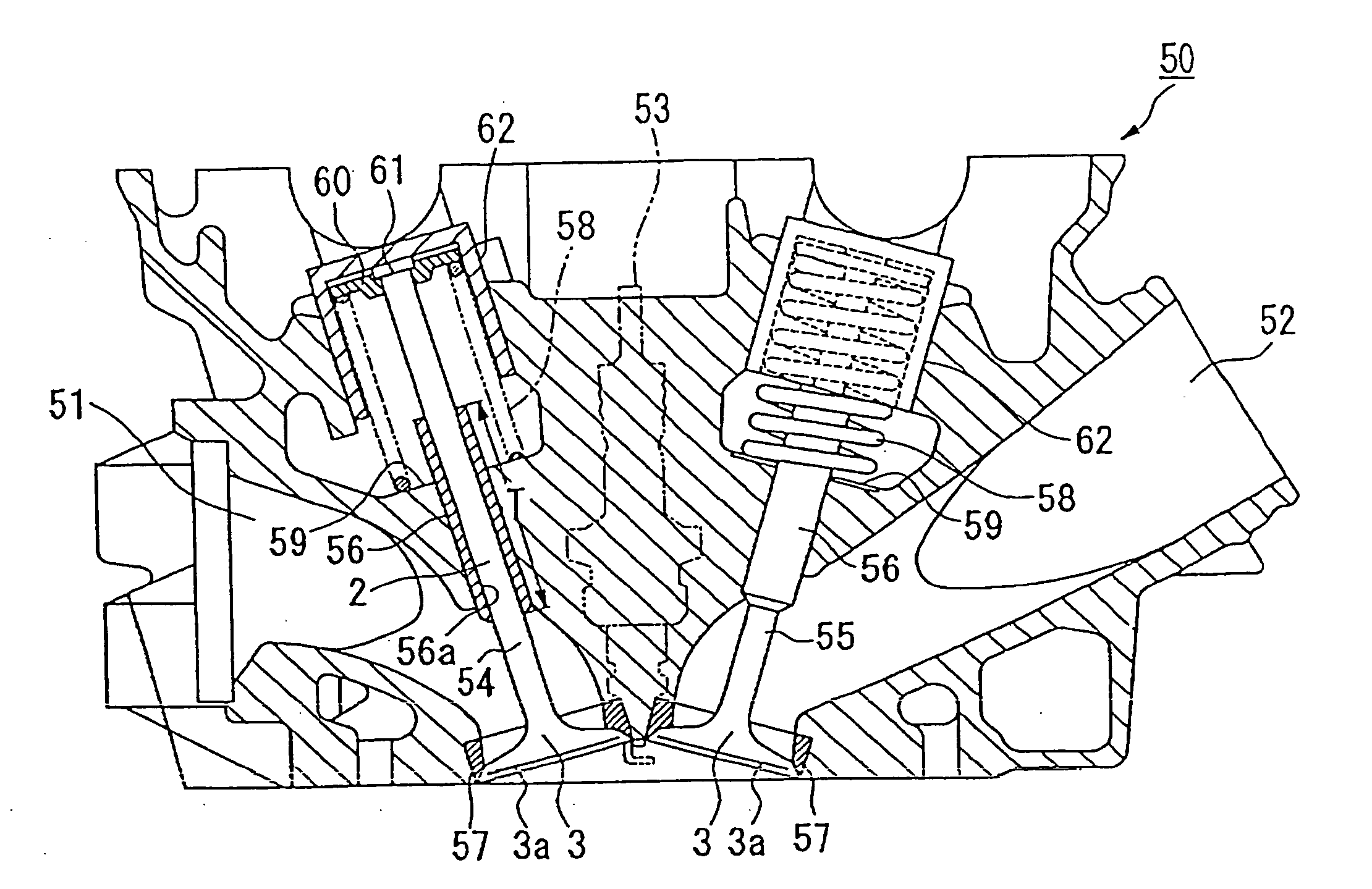
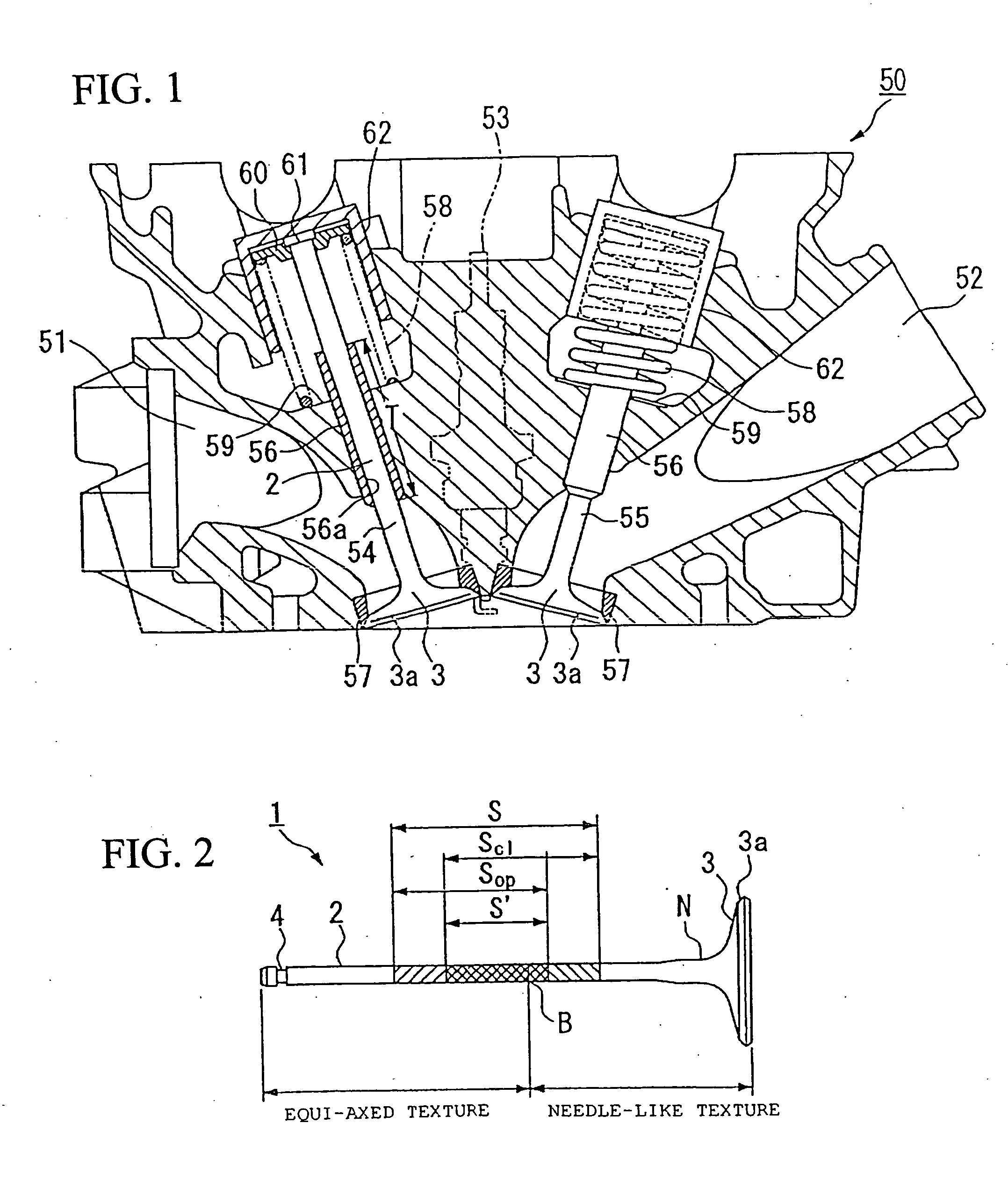
[0026] A cylinder head 50, which constitutes a portion of a valve system of an internal combustion engine, shown in FIG. 1, will be described first.

[0027] The cylinder head 50 is provided with an air-intake port 51 and an exhaust port 52 which communicate, respectively, with a combustion chamber of a cylinder block (not shown) in the assembled engine. A gaseous air-fuel mixture is drawn in through the air-intake port 51 and into the combustion chamber. After combustion, exhaust gas from the combustion chamber is discharg...


PUM

PropertyMeasurementUnit
Temperatureaaaaaaaaaa
Structureaaaaaaaaaa

Abstract

An engine valve, formed of a titanium alloy, enables improvement of reliability and productivity while improving creep resistance and fatigue strength at a high temperature. The engine valve, including a stem section and a bevel section provided at one end of the stem section, is integrally formed of the titanium alloy. A portion of the valve, extending from the bevel section to a medial portion of the valve stem, is formed mainly of a needle-like crystallographic texture. Another portion of the valve, extending from the medial section to the other end of the stem section, is formed of a material having a substantially equiaxed crystallographic texture. A boundary between the needle-like texture and the equiaxed texture is provided in a range of sliding movement of the valve relative to a valve guide that slidably guides the stem section within the cylinder head.

Description

CROSS-REFERENCE TO RELATED APPLICATIONS [0001] The present invention claims priority under 35 USC 119 based on Japanese Patent Application No. 2005-279441, filed on Sep. 27, 2005. The subject matter of this priority document is incorporated by reference herein. BACKGROUND OF THE INVENTION [0002] 1. Field of the Invention [0003] The present invention relates to an engine valve formed of titanium alloy used for an internal combustion engine, the engine used, for example, in an automotive vehicle. The present invention also relates to a method of making the engine valve, and to a cylinder head incorporating the valve. [0004] 2. Description of the Background Art [0005] Hitherto, in order to improve a performance of an engine, attempts have been made to increase the engine's usable rotary speed range. The largest obstacle for enhancing the permissible number of engine revolutions over a period of time is an increase in inertial mass of a valve system. In other words, an increase in the i...

Claims


Application Information

Patent Timeline
IPC IPC(8): F02N3/00F02F1/00
CPCB21J1/06F01L3/02B23P15/002B21K1/22
Inventor MARUI, YUJIOKAMOTO, NAOYA
Owner HONDA MOTOR CO LTD
Why Eureka
Try Eureka