Optical device and image display apparatus

an image display and optical device technology, applied in the field of optical devices and image display apparatuses, can solve the problems of reducing the resolution of the display image to be guided to the eye, difficult to achieve different diffraction efficiencies, and difficulty in providing interference fringes, so as to reduce the length of the first diffraction grating member, reduce the thickness of the light guide plate, and increase the range of incident angles

Inactive Publication Date: 2007-03-29
SONY CORP
View PDF3 Cites 146 Cited by
  • Summary
  • Abstract
  • Description
  • Claims
  • Application Information

AI Technical Summary

Benefits of technology

[0030] Alternatively, in the above-referenced embodiments of the present invention, the first diffraction grating member may include diffraction grating layers defined by Q layers of reflective volume hologram diffraction gratings, Q being an integer. In that case, the interference fringes are provided in each of the diffraction grating layers of the first diffraction grating member and extend from within each diffraction grating layer towards surfaces thereof. Moreover, the interference fringes on the surfaces of each diffraction grating layer are arranged at an equal pitch, and the interference fringes in the diffraction grating layers are arranged at the same pitch. This multilayer structure contributes to a reduction in length of the first diffraction grating member in the axial direction of the light guide plate, a thickness reduction of the light guide plate, and an increased range of incident angles for collimated beams that can be diffracted and reflected by the first diffraction grating member.

Problems solved by technology

Moreover, since interference fringes to be formed on the transmissive hologram lens 103 have a complicated pattern with an aspherical phase component, it is difficult to provide the interference fringes in multiple numbers to increase the acceptable angle for diffraction by the transmissive hologram lens 103 in order to increase the pupil diameter, or is difficult to give the transmissive hologram lens 103 a multilayer structure.
This implies that, at the same wavelength and at the same incident angle, it is difficult to attain different diffraction efficiencies while maintaining an equal diffraction angle.
This may cause a monochromatic eccentric aberration to a large degree, which can reduce the resolution of a display image to be guided to the eye.
This problem leads to a significant limiting condition that permits only the use of a light source having a narrow wavelength range.

Method used


Image

  • Optical device and image display apparatus
  • Optical device and image display apparatus
  • Optical device and image display apparatus

Examples


first embodiment

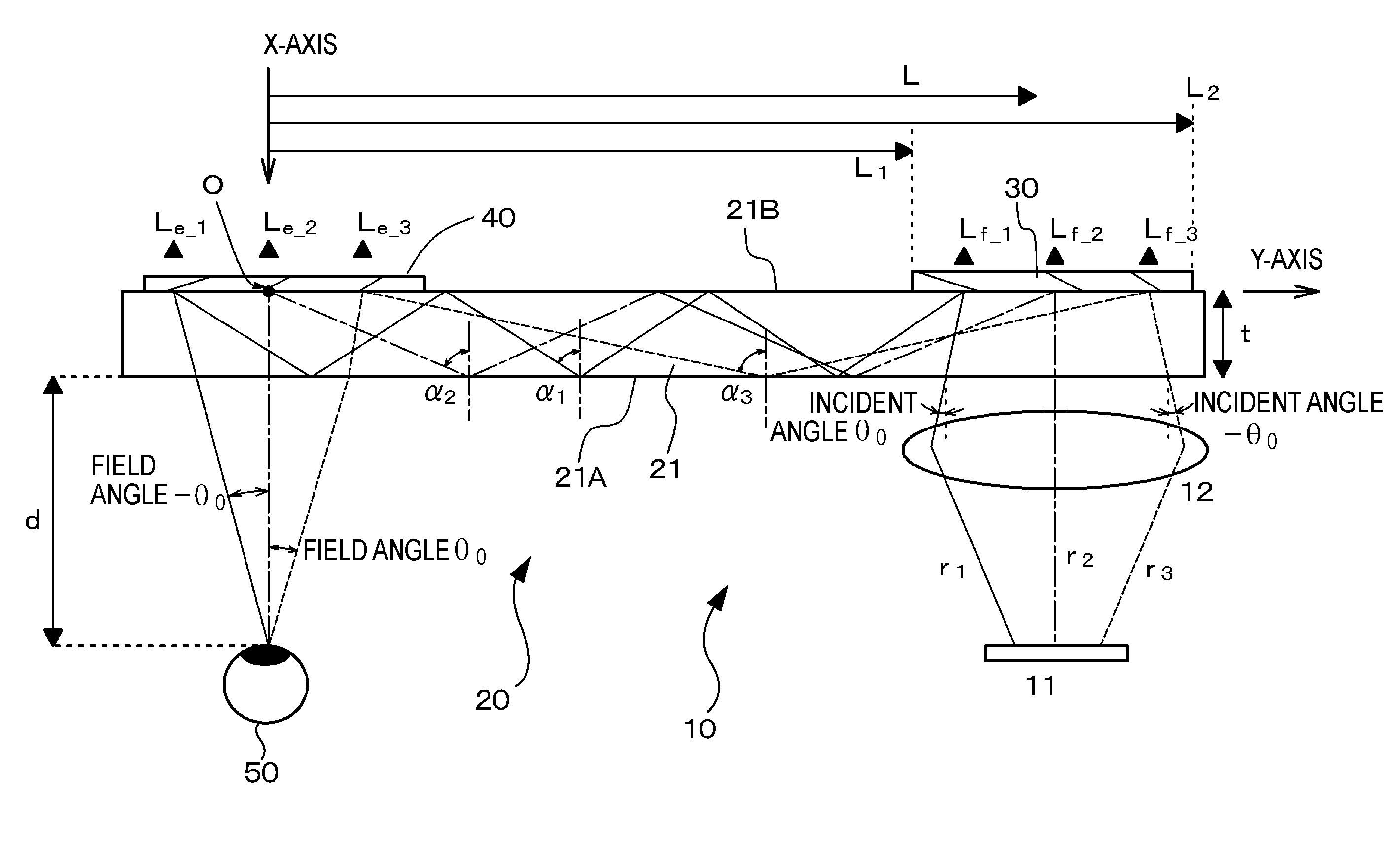
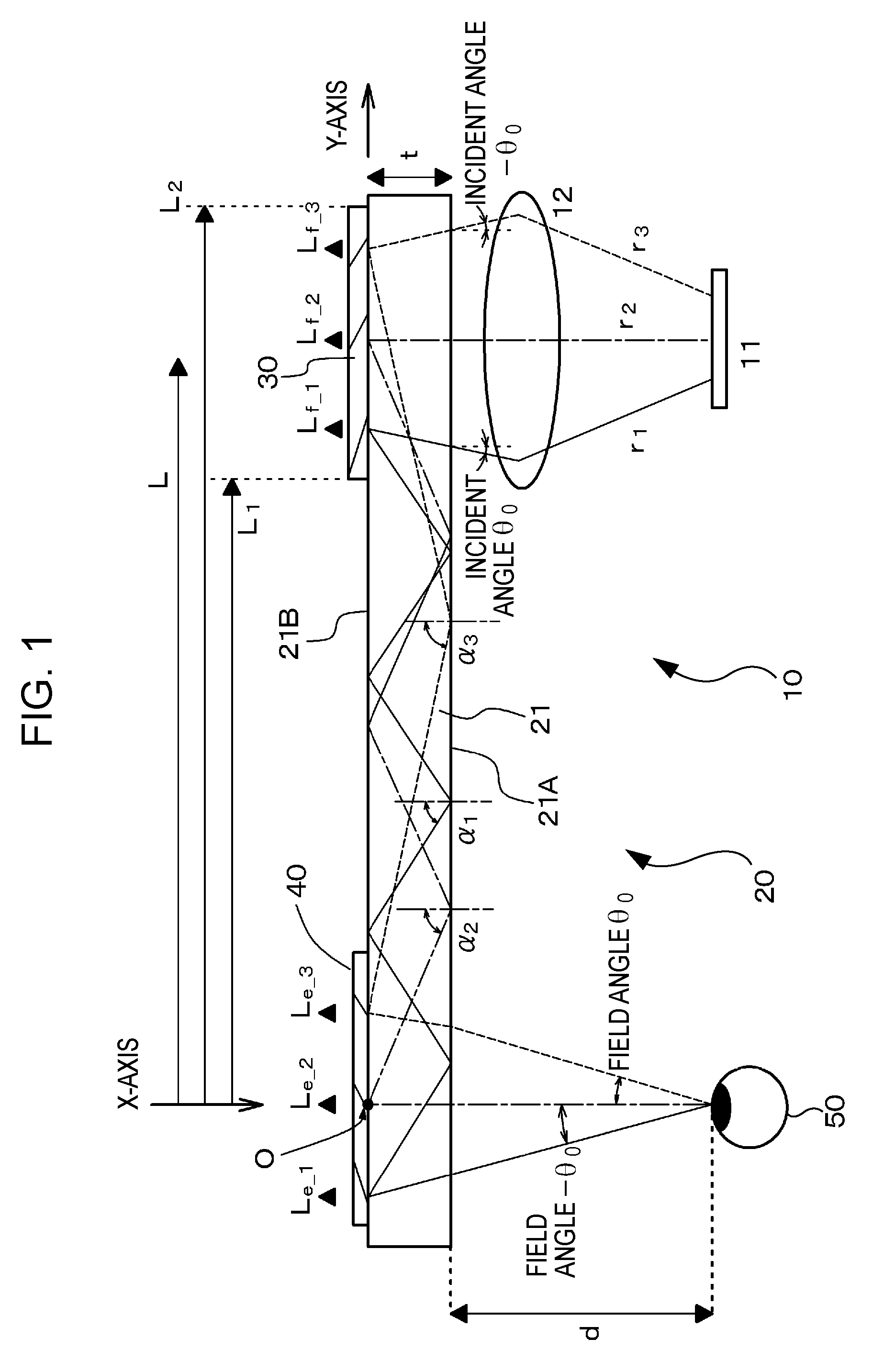
[0083] A first embodiment of the present invention relates to an optical device and an image display apparatus. FIG. 1 schematically illustrates an optical device 20 and an image display apparatus 10 according to the first embodiment of the present invention.

[0084] The image display apparatus 10 according to the first embodiment includes an image forming device 11, a collimator optical unit 12 configured to collimate light beams emitted from the image forming device 11, and the optical device 20 which receives the plurality of collimated beams collimated and oriented in different directions by the collimator optical unit 12, and then guides and emits the collimated beams. The image forming device 11 is, for example, a liquid-crystal display device (LCD). The collimator optical unit 12 is, for example, a convex lens. In order to produce a collimated beam group that includes the plurality of collimated beams traveling in different directions, the image forming device 11 is disposed a...

second embodiment

[0109] A second embodiment is a modification of the first embodiment. In the second embodiment, the various parameters shown in Table 3 of the first embodiment are changed to parameters shown in Table 6 below.

TABLE 6Thickness t of Light Guide Plate 21:6 mmEye Relief d:20 mmPitch of Interference Fringes of First Diffraction Grating402.2 nmMember 30:Field Angle θ0:3.5°Field Angle −θ0:−3.5°

[0110]FIG. 3A is a graph that shows at which point in the first diffraction grating member 30 a collimated beam with a wavelength λ of 522 nm is diffracted and reflected before entering the center of the eye 50, and also shows the number of times the collimated beam undergoes total reflection off the second surface 21B of the light guide plate 21 before reaching the eye 50.

[0111] In FIG. 3A, an upward-sloping solid curve [1] corresponds to a case where the number of times N of total reflection is 3, and an upward-sloping dotted curve [2] corresponds to a case where the number of times N of total r...

third embodiment

[0119] A third embodiment is also a modification of the first embodiment. In the third embodiment, the various parameters shown in Table 3 of the first embodiment are changed to parameters shown in Table 9 below.

TABLE 9Thickness t of Light Guide Plate 21:5 mmEye Relief d:20 mmPitch of Interference Fringes of First Diffraction Grating402.2 nmMember 30:Field Angle θ0:6.0°Field Angle −θ0:−6.0°

[0120] In the third embodiment, the first diffraction grating member 30 includes diffraction grating layers 30A, 30B defined by Q layers of reflective volume hologram diffraction gratings (Q=2 in the third embodiment). Each of the diffraction grating layers 30A, 30B included in the first diffraction grating member 30 has interference fringes extending from within the diffraction grating layer 30A, 30B towards surfaces thereof. The interference fringes on the surfaces of each of the diffraction grating layers 30A, 30B of the first diffraction grating member 30 are arranged at an equal pitch. More...


PUM


Abstract

An optical device includes a light guide plate, and first and second reflective volume hologram diffraction grating members. The first member has interference fringes extending from therewithin towards surfaces thereof and arranged at an equal pitch. Each interference fringe and each surface of the first member form an inclination angle therebetween. The first member has the following conditions. (a) In an outer region positioned farther away from the second member than a minimum inclination angle region having a minimum inclination angle, the inclination angles of the interference fringes increase with increasing distance from the minimum inclination angle region. (b) In an inner region positioned closer to the second member than the minimum inclination angle region, the inclination angles of the interference fringes include a maximum inclination angle in an inner area disposed adjacent to the minimum inclination angle region and decrease with increasing distance from the minimum inclination angle region.

Description

CROSS REFERENCES TO RELATED APPLICATIONS [0001] The present invention contains subject matter related to Japanese Patent Application JP 2005-285397 filed in the Japanese Patent Office on Sep. 29, 2005, the entire contents of which are incorporated herein by reference. BACKGROUND OF THE INVENTION 1. Field of the Invention [0002] The present invention relates to an optical device that allows an observer to observe a two-dimensional image formed by an image forming device, and to an image display apparatus equipped with the optical device. [0003] 2. Description of the Related Art [0004] PCT Japanese Translation Patent Publication No. 8-507879 and Japanese Unexamined Patent Application Publication No. 2002-162598 disclose known examples of a virtual-image display apparatus equipped with a hologram diffraction grating. Such an apparatus allows an observer to observe a two-dimensional image formed by an image forming device as a virtual image magnified by a virtual-image optical system. [...

Claims


Application Information

Patent Timeline
Patent Type & Authority Applications(United States)
IPC IPC(8): G02B5/18
CPCG02B5/1861G02B5/32G02B27/0172G02B2027/0174G02B2027/0116G02B2027/0125G02B27/022G02B27/4272G02B5/18G02B6/00G02B27/00
Inventor AKUTSU, KATSUYUKIMUKAWA, HIROSHI
Owner SONY CORP
Why Eureka
Try Eureka