Lithium secondary battery, negative electrode therefor, and method of their manufacture

a secondary battery and negative electrode technology, applied in cell components, electrochemical generators, transportation and packaging, etc., can solve the problems of poor discharge capacity, poor charge-discharge cycle performance, and component in the negative electrode mixture layer increases, so as to achieve good discharge capacity, less electrical resistance, and good charge-discharge cycle performance

Inactive Publication Date: 2007-03-29
SANYO ELECTRIC CO LTD
View PDF6 Cites 29 Cited by
  • Summary
  • Abstract
  • Description
  • Claims
  • Application Information

AI Technical Summary

Benefits of technology

[0009] Accordingly, it is an object of the present invention to provide a practical lithium secondary battery that has a greater battery capacity than in the case of using particulate graphite as the negative electrode active material but a less electrical resistance of the negative electrode mixture layer than in the case of using particulate Si as the negative electrode active material, while achieving good charge-discharge cycle performance, and to provide a method of manufacturing the battery. It is another object of the invention to provide a negative electrode for use in the lithium secondary battery according to the invention, and a method of manufacturing the electrode.

Problems solved by technology

As a consequence, the current collection performance in the negative electrode degrades, resulting in poor charge-discharge cycle performance.
Nevertheless, because the negative electrode active material has a high content of silicon, the current collection performance in the negative electrode mixture layer lowers in the last stage of discharge when the negative electrode mixture layer shrinks, and the resistance component in the negative electrode mixture layer increases.
This leads to the problem of poor discharge capacity.
In addition, when the negative electrode mixture layer contains a binder and particulate Sn, which can intercalate Li most among the Sn-based particulate active materials and has high conductivity, heat-treating to the negative electrode mixture layer leads to the following problems.
Firstly, the Sn in the Sn particles reacts with a metal component (mainly copper) in the negative electrode current collector, causing degradation in the mechanical strength of the negative electrode current collector or adhering of the electrodes to each other.

Method used


Image

  • Lithium secondary battery, negative electrode therefor, and method of their manufacture
  • Lithium secondary battery, negative electrode therefor, and method of their manufacture
  • Lithium secondary battery, negative electrode therefor, and method of their manufacture

Examples


example 1

Preparation of Negative Electrode

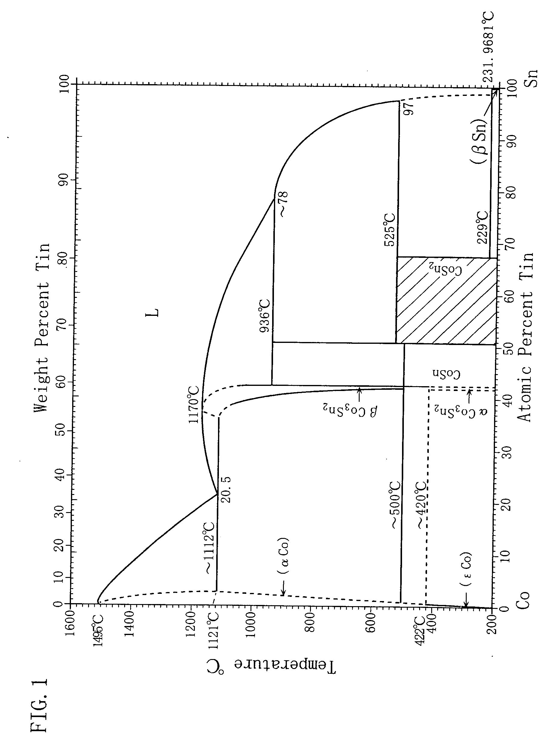
[0050] A particulate negative electrode active material containing the CoSn phase and the CoSn2 phase at a molar ratio of 1:1 (average particle size: 10 μm) were mixed into an N-methyl-2-pyrrolidone solution in which PVdF was dissolved at 8 mass %, to thus prepare a negative electrode mixture slurry. The solid mass ratio of the particulate negative electrode active material to the PVdF in the negative electrode mixture slurry was adjusted to be 93:7 (solid volume ratio: 75:25).

[0051] The resultant negative electrode mixture slurry was applied onto one side (the roughened surface side) of an electrolytic copper foil (thickness: 35 μm) having a surface roughness Ra of 1.0 μm and serving as a negative electrode current collector, and thereafter the negative electrode mixture slurry was dried. The resultant layered material was cut out into dimensions of 20 mm×20 mm and then pressure-rolled. Thereafter, the resultant material was heated (heat-treated)...

example2

[0056] A negative electrode and a battery were fabricated in the same manner as in Example 1 above, except that powder (average particle size: 10 μm) composed only of the Co2—Sn phase was used as the particulate negative electrode active material.

[0057] The negative electrode and the battery thus prepared are hereinafter referred to as a negative electrode a2 of the invention and Battery A2 of the invention.

experiment 1

[0066] A charge-discharge test was conducted under the charge-discharge test conditions set out below, to determine initial charge capacity per unit mass of negative electrode active material (hereafter also simply referred to as “initial charge capacity”) and discharge capacity retention ratio after 5 cycles (hereafter also simply referred to as “discharge capacity retention ratio”) for the foregoing batteries. The results are shown in Table 2 below. It should be noted that the discharge capacity retention ratio after 5 cycles means the ratio of discharge capacity after 5 cycles to initial discharge capacity as defined by the following equation (1).

Discharge capacity retention ratio after 5 cycles=Discharge capacity after 5 cycles / Initial discharge capacity×100  Eq. (1)

Charge-discharge Test Conditions

[0067] Conditions of charge (lithium insertion to negative electrode)

[0068] The batteries were charged at a constant current of 0.1 mA / cm2 to an end-of-charge voltage of 0.0 V (vs. ...


PUM

PropertyMeasurementUnit
surface roughness Raaaaaaaaaaa
mass %aaaaaaaaaa
particle sizeaaaaaaaaaa

Abstract

A practical lithium secondary battery is provided having a greater battery capacity than in the case of using particulate graphite as its negative electrode active material but a less electrical resistance of its negative electrode mixture layer than in the case of using particulate Si as the negative electrode active material. The lithium secondary battery also exhibits good charge-discharge cycle performance. The lithium secondary battery is furnished with a negative electrode having negative electrode current collector and a negative electrode mixture layer that contains a Sn-based particulate negative electrode active material and a negative electrode binder. The negative electrode binder is melt-bonded to the Sn-based particulate negative electrode active material and / or the negative electrode current collector, and the Sn-based particulate negative electrode active material is made of an intermetallic compound represented as SnXM1-X, where 1>X≧1 / 2 and M is Mn, Fe, Co, or Ni.

Description

BACKGROUND OF THE INVENTION [0001] 1. Field of the Invention [0002] The present invention relates to lithium secondary batteries and methods of manufacturing the batteries, and more particularly to negative electrodes for lithium secondary batteries and methods of manufacturing the electrodes. [0003] 2. Description of Related Art [0004] In recent years, lithium secondary batteries using a non-aqueous electrolyte and performing charge-discharge operations by transferring lithium ions between positive and negative electrodes have been utilized as a new type of high power, high energy density secondary battery. In this type of lithium secondary battery, the negative electrode generally has a structure in which a negative electrode current collector and a negative electrode active material layer containing graphite are stacked. In recent years, much research has been conducted on negative electrode active material to increase the capacity of a lithium secondary battery. The use of mater...

Claims


Application Information

Patent Timeline
Patent Type & Authority Applications(United States)
IPC IPC(8): H01M4/38H01M4/62H01M4/02H01M4/134H01M4/1395H01M4/64H01M10/05
CPCH01M4/136H01M4/621H01M4/623Y10T29/49108Y02E60/122Y02T10/7011H01M10/052Y02E60/10Y02T10/70
Inventor KUSUMOTO, YASUYUKISAKITANI, NOBUHIRO
Owner SANYO ELECTRIC CO LTD
Why Eureka
Try Eureka