Electromagnetic Coupling Device Having Conducting Bearing And Lubricant

a technology of conducting bearing and lubricant, which is applied in the direction of fluid clutches, clutches, non-mechanical actuated clutches, etc., can solve the problems of less efficient magnetic flux path, less device complexity, and low reliability and durability, so as to reduce the number of parts and variable costs, improve reliability and durability, and improve the effect of magnetic and corresponding electric efficiency

Inactive Publication Date: 2007-04-12
FORD GLOBAL TECH LLC
View PDF11 Cites 5 Cited by
  • Summary
  • Abstract
  • Description
  • Claims
  • Application Information

AI Technical Summary

Benefits of technology

[0007] The present invention provides a number of advantages. For example, the present invention reduces part count and variable cost by using conductive lubricating grease in a bearing to provide a direct electrical conduction path to a rotating electromagnetic coil. Elimination of parts, such as brushes and slip rings may substantially improve reliability and durability. Use of a rotating coil according to the present invention allows embedding of the coil within one of the rotating members

Problems solved by technology

These components add to the device complexity, cost, and part count, and can have durability issues.
Alternatively, stationary coil designs have a less efficient magnetic flux path that must traverse at least one, and typically two, air gaps and therefore require expensive precision machining to minimize the air gap while still providing sufficient clearance to accom

Method used


Image

  • Electromagnetic Coupling Device Having Conducting Bearing And Lubricant
  • Electromagnetic Coupling Device Having Conducting Bearing And Lubricant

Examples


Embodiment Construction

)

[0011] As those of ordinary skill in the art will understand, various features of the present invention as illustrated and described with reference to any one of the Figures may be combined with features illustrated in one or more other Figures to produce embodiments of the present invention that are not explicitly illustrated or described. The combinations of features illustrated provide representative embodiments for typical applications. However, various combinations and modifications of the features consistent with the teachings of the present invention may be desired for particular applications or implementations.

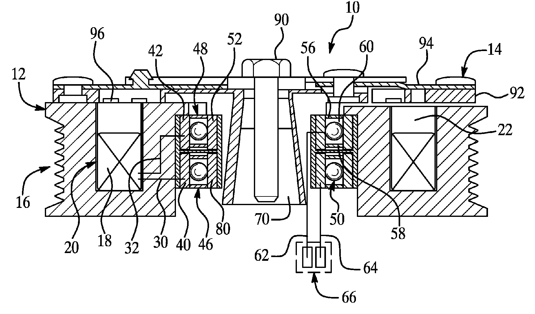
[0012]FIG. 1 is a split-view cross-section illustrating operation and construction of an electromagnetic friction clutch embodiment of an electromagnetic coupling device according to the present invention. As previously described, an electromagnetic coupling device according to the present invention may be used to selectively couple two rotating components when opera...


PUM


Abstract

An electromagnetic coupling device includes a rotating member having an embedded coil positioned to provide a magnetic flux path through the rotating member while substantially eliminating at least one air gap to improve efficiency. At least one bearing or bushing assembly disposed between the rotating member and a second member includes an electrically conductive lubricant to supply electrical current through the assembly and lubricant to the embedded coil during actuation of the device. A method of making an electromagnetic coupling device includes embedding a coil within a rotating member such that the rotating member contacts substantially the entire outer surface of the coil to provide an efficient magnetic flux path and thermal conductivity for heat dissipation through the rotating member and connecting the embedded coil to at least one conductive bearing assembly having conductive lubrication grease.

Description

BACKGROUND OF THE INVENTION [0001] 1. Field of the Invention [0002] The present invention relates to electromagnetic coupling devices. [0003] 2. Background Art [0004] An electromagnetic (EM) coupling device may be used as a clutch or brake to selectively couple a rotating component to either another rotating component (operating as a clutch), or to a stationary component (operating as a brake). EM clutches / brakes require a wire coil to be energized by an external source of electric current to create a magnetic field used to couple the components. EM clutch / brake designs include either a rotating coil embedded in one of the rotating members, or a stationary coil placed between the selectively coupled members. In general, rotating coil designs have a more efficient magnetic flux path, but must be connected to the electric current source using brushes or slip-rings. These components add to the device complexity, cost, and part count, and can have durability issues. Alternatively, stati...

Claims


Application Information

Patent Timeline
IPC IPC(8): F16D35/02F16D27/02
CPCF16D27/06F16D37/008
Inventor ELIE, LARRYMARANVILLE, CLAYGINDER, JOHN
Owner FORD GLOBAL TECH LLC
Why Eureka
Try Eureka