Production of nanoparticles and microparticles

a technology applied in the field of nanoparticles and microparticles, can solve problems such as adverse effects on their characteristics

Inactive Publication Date: 2007-04-12
PARKANSKY NAHUM +1
View PDF3 Cites 34 Cited by
  • Summary
  • Abstract
  • Description
  • Claims
  • Application Information

AI Technical Summary

Problems solved by technology

These voids may adversely affect their characteristics.

Method used


Image

  • Production of nanoparticles and microparticles
  • Production of nanoparticles and microparticles
  • Production of nanoparticles and microparticles

Examples


examples

[0090] Reference is now made to the following examples, which together with the above descriptions, illustrate the invention in a non-limiting fashion. Exemplary particles were produced using the common features / parameters detailed in Table 1.

TABLE 1Common Features in the ExamplesParameter or FeatureValueVesselPlastic Cup, 60 ml volumeLiquidEthyl Alcohol (C2H5OH)ModeContact ModePeak Arc Current100APulse Duration20μsRepetition Rate100HzProcessing Time5min

[0091] The results obtained for various examples of particle production, using the common features detailed in Table 1, are presented in Table 2. The results include a characterization of the particles, along with a brief description of the particulars of the production and collection thereof.

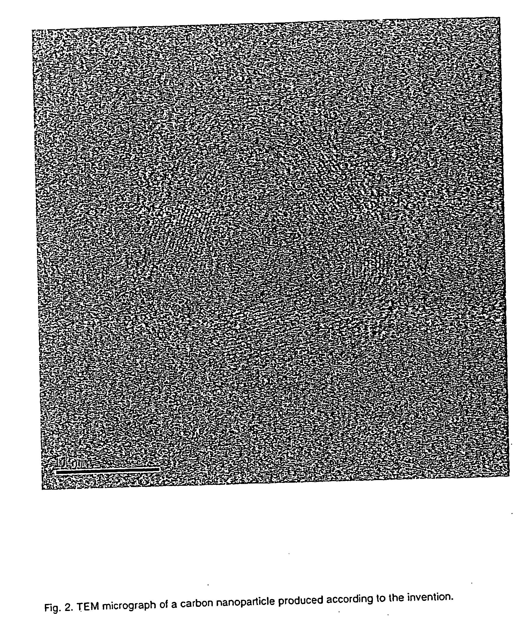
TABLE 2Examples of produced particlesElect. 1Elect.cross-Elect. 2ParticleParticleMicrographExMat.section, mmsize, mmCollectionDescriptionsizeFeature SizeFig.1C1 × 410 × 10TopC nano-particle˜20nmCavity-5 nm22Ni5 × 2.580 × 5PrecipitateBall wit...


PUM

PropertyMeasurementUnit
current amplitudeaaaaaaaaaa

Abstract

A method of producing microparticles including: (a) providing a system including: (i) a vessel containing a liquid; (ii) at least a first pair of electrodes; (iii) a mechanism for igniting an electrical arc between the electrodes; (b) disposing the first pair of electrodes within the liquid, and (c) effecting at least one pulsed electrical discharge between the electrodes so as to produce a plasma bubble, and to produce the microparticles, the microparticles being associated with the plasma bubble, wherein the pulsed electrical discharge has a pulse duration of less than 1000 microseconds, and wherein the pulsed electrical discharge has a current amplitude of at least 1 ampere (A).

Description

FIELD AND BACKGROUND OF THE INVENTION [0001] The present invention relates to nanoparticles and microparticles and, more particularly, to a method for producing solid particles with sizes in the nm-μm range. [0002] Nanoparticles and microparticles are becoming increasingly important in various technological applications, inter alia, paints and inks, powder metallurgy, drug delivery, and dry lubricants. Paints and inks are often composed of particles, suspended in a liquid carrier. After being applied to a surface, the liquid carrier evaporates, leaving a solid residue composed of the conglomerated particles. In some technological applications, it is advantageous to have particles with particular electrical or magnetic properties. For example, particles with a high magnetic permeability may be useful in paints that absorb electromagnetic radiation, e.g., radar waves. Particles having an electrical charge may be useful in printing processes in which the direction of the ink jet is con...

Claims


Application Information

Patent Timeline
Patent Type & Authority Applications(United States)
IPC IPC(8): H05F3/00B01J19/08B01JB81C99/00C22C29/02
CPCB01J8/005B01J19/088B01J2219/0813B01J2219/0839B01J2219/0841B01J2219/0849B01J2219/0867B01J2219/0877B01J2219/0894B22F1/0044B22F9/14B22F2998/00B22F2999/00B82Y30/00C01B31/02H05H1/48B22F2207/07B22F2202/13B22F2202/01C01B32/05B22F1/07
Inventor PARKANSKY, NAHUMBOXMAN, RAYMON LEON
Owner PARKANSKY NAHUM
Why Eureka
Try Eureka