Radiation imaging apparatus, radiation imaging system, and program

a radiation imaging and program technology, applied in the direction of x/gamma/cosmic radiation measurement, instruments, radiography controlled devices, etc., can solve the problems of reducing the frame rate of normal drive, affecting the sensitivity of fpd, delay and waveform distortion of scanning-line driving signals, etc., to achieve accurate, high-s/n-ratio x-ray radiographic images and excellent images.

Inactive Publication Date: 2007-04-12
CANON KK
View PDF31 Cites 60 Cited by
  • Summary
  • Abstract
  • Description
  • Claims
  • Application Information

AI Technical Summary

Benefits of technology

[0022] The present invention make it possible that, in accordance with a plurality of radiographing conditions such as the still image radiographing mode and the moving image radiographing mode, the outputs both in the irradiation period and in the non-irradiation period are made to fall within the dynamic range of the radiographing system. Accordingly, an accurate, high-S/N-ratio X-ray radiographic image can be obtained. The present invention makes it possible that a single X-ray imagin

Problems solved by technology

In moving image radiographing (fluoroscopic radiographing), because, compared with still image radiographing, radiations are continuously irradiated onto a patient for a long time, it is required to consider the reduction of patient exposure, whereby, compared with still image radiographing, enhancement of sensitivity of the FPD is an issue.
In the case of U.S. Pat. No. 6,185,274, the resistan

Method used


Image

  • Radiation imaging apparatus, radiation imaging system, and program
  • Radiation imaging apparatus, radiation imaging system, and program
  • Radiation imaging apparatus, radiation imaging system, and program

Examples


embodiment 1

[0035] (Embodiment 1)

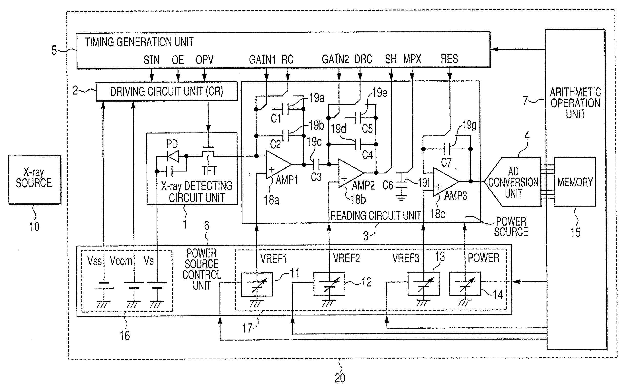
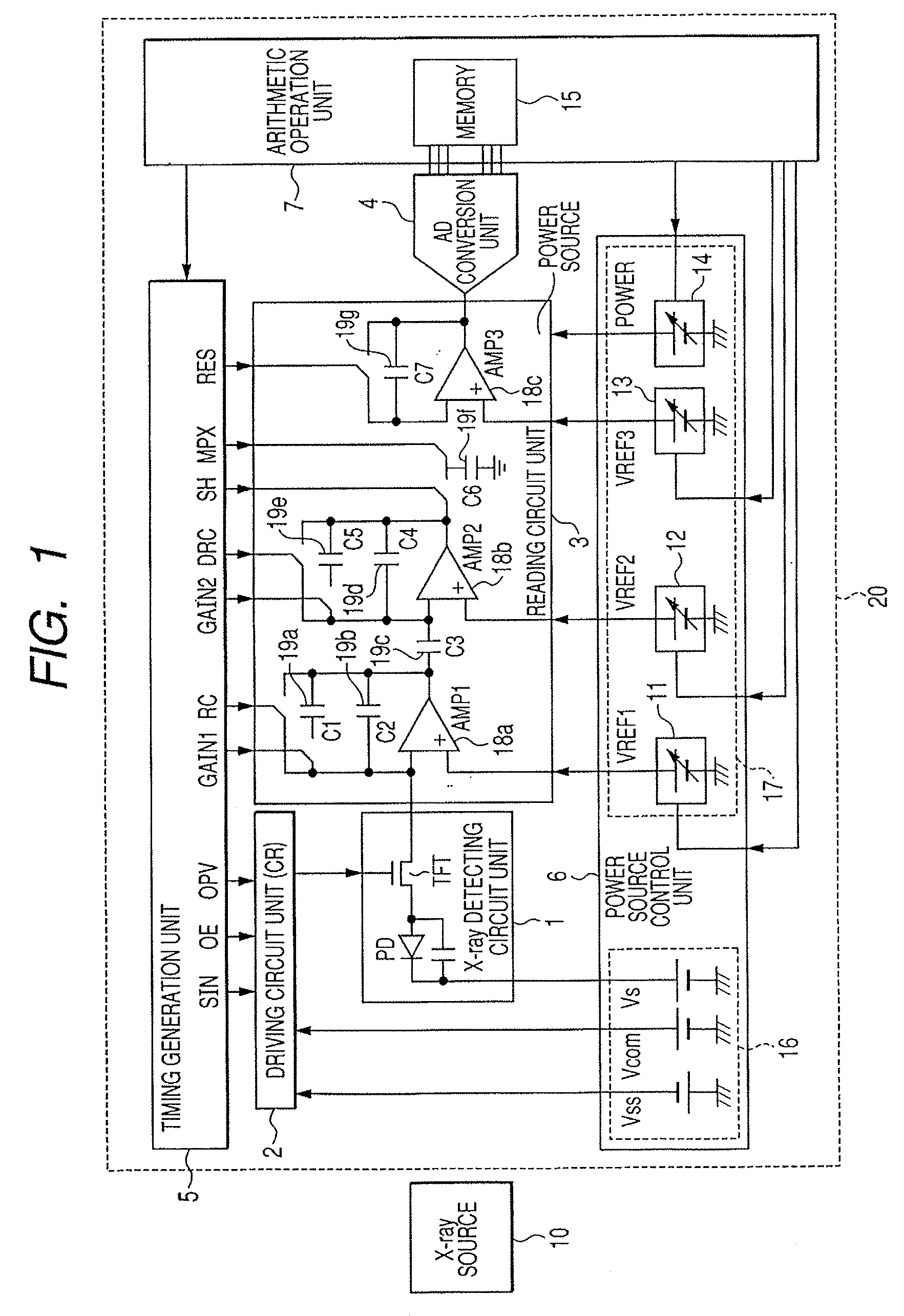
[0036]FIG. 1 is a schematic block diagram illustrating an X-ray imaging system according to Embodiment 1 of the present invention. The X-ray imaging system is configured of an X-ray source 10 for irradiating X-rays onto a subject, an X-ray imaging apparatus 20 for picking up X-rays that have passed through (or that have been reflected by) a subject, and an unillustrated control unit for controlling the drive of the X-ray source 10 and the X-ray imaging apparatus 20.

[0037] In the X-ray imaging apparatus 20, Reference Numeral 1 denotes an X-ray detecting circuit unit for detecting X-rays from a subject. The X-ray detecting circuit unit 1 is configured of a plurality of pixels, juxtaposed in a two-dimensional array fashion, that are each made up of an X-ray detecting element (conversion element) and a switching element for selecting the X-ray detecting element. In Embodiment 1, the X-ray detecting element has a photoelectric conversion element, and a thin-film tra...

embodiment 2

[0082] (Embodiment 2)

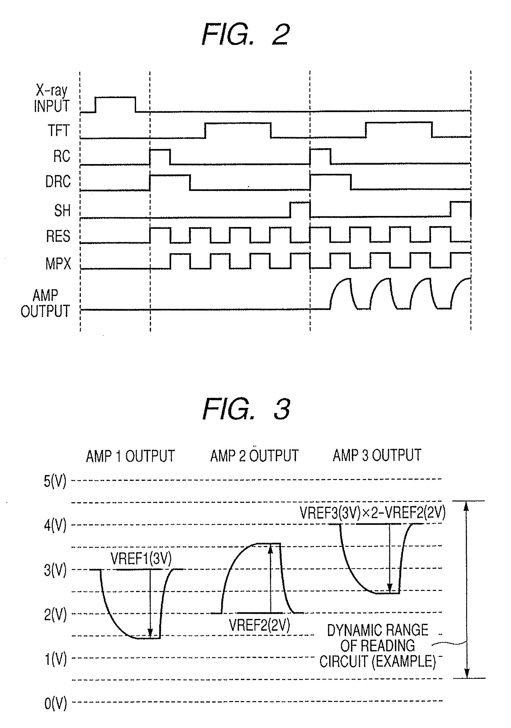
[0083] In the present embodiment, a case will be explained in which, in the X-ray imaging apparatus in FIG. 1, VREF1 of the variable power source 11 is changed instead of VREF2 and VREF3. In other words, the arithmetic operation unit 7 changes VREF1 such that the maximal value or the minimal value, of the output, in the irradiation period and the maximal value or the minimal value, of the output, in the non-irradiation period fall within the dynamic ranges of the reading circuit unit 3 and the Analogue-Digital conversion unit 4.

[0084] In the case of the configuration illustrated in FIG. 1, the reference electric potential VREF1 is the output, of the AMP 18a, illustrated in FIG. 3; however, as illustrated associated with the AMP 18c, the last-stage output level at dark is not a function of VREF1. For example, in the case of the moving image radiographing mode, it is required to decrease the X-ray quantity in view of reduction of patient exposure; therefore, in o...

embodiment 3

[0090] (Embodiment 3)

[0091] In the present embodiment, in the X-ray imaging apparatus in FIG. 1, the minimal value of the output at dark and the maximal value of the output at light are each made to be a function of radiographing parameters that configure the radiographing condition. The minimal value of the output at dark and the maximal value of the output at light, which have been made to be functions, are stored in the memory 15 in the arithmetic operation unit 7. Subsequently, the arithmetic operation unit 7 changes the reference electric potentials such that the maximal value of the output at light and the maximal value of the output at light, which have been made to be functions, fall within the dynamic ranges of the reading circuit unit 3 and the Analogue-Digital conversion unit 4.

[0092] The output at light (X-ray output) in the X-ray irradiation period and the output at dark in the X-ray non-irradiation period are functions of the radiographing parameters. For example, the...


PUM


Abstract

It is made possible that, in accordance with a plurality of radiographing modes such as the still image radiographing mode and the moving image radiographing mode, the outputs both in the irradiation period and in the non-irradiation period are made to fall within the dynamic range of the radiographing system, whereby an accurate, high-S/N-ratio X-ray radiographic image is obtained. For that purpose, in accordance with the plurality of radiographing modes, an arithmetic operation unit adjusts a power source to control voltage to be applied to a reading circuit unit or an Analogue-Digital conversion unit, such that, in each of the radiographing modes, both an electric signal in the X-ray irradiation period and an electric signal in the X-ray non-irradiation period fall within the dynamic ranges of the reading circuit unit and the Analogue-Digital conversion unit.

Description

BACKGROUND OF THE INVENTION [0001] 1. Field of the Invention [0002] The present invention relates to a radiation imaging apparatus, a radiation imaging system, and a program that are suitably used, e.g., in medical diagnosis, industrial non-destructive inspection, and the like. In addition, in the present specification, it is assumed that “radiations” include electromagnetic waves, such as an X-ray, and a γ-ray, an α-ray, and a β-ray. [0003] 2. Description of the Related Art [0004] Radiation imaging systems that have been installed in hospitals, clinics, or the like are categorized into an analogue and a digital radiographing method. In the analogue radiographing method, radiations such as X-rays are irradiated onto a patient and a film is exposed by the radiations that have passed through the patient. In the digital radiographing method, radiations that have passed through the patient are converted into electric signals, i.e., digital data so as to obtain image data. [0005] The dig...

Claims


Application Information

Patent Timeline
IPC IPC(8): G01T1/24
CPCG01T1/2018G01T1/247G01T1/20184
Inventor ENDO, TADAOKAMESHIMA, TOSHIOYAGI, TOMOYUKITAKENAKA, KATSUROYOKOYAMA, KEIGO
Owner CANON KK
Why Eureka
Try Eureka