High current, multiple air gap, conduction cooled, stacked lamination inductor

a technology of inductor and air gap, which is applied in the direction of transformer/inductance details, inductances with magnetic cores, inductances with high losses, etc., can solve the problems of increasing the current with which the permeability of the powder core drop becomes unacceptable, limiting the effectiveness of the powder magnetic core material to reduce the temperature of the inductor, and exhibiting high losses around the air gap. , to achieve the effect of minimizing eddy current losses, efficien

Active Publication Date: 2007-04-12
HAMILTON SUNDSTRAND CORP
View PDF3 Cites 30 Cited by
  • Summary
  • Abstract
  • Description
  • Claims
  • Application Information

AI Technical Summary

Benefits of technology

[0011] The present invention therefore provides a power inductor assembly which efficiently conducts heat from the magnetic core while minimizing eddy current losses and maintaining a desired inductance level.

Problems solved by technology

This type of inductor contains a magnetic core and typically exhibits high losses around the air gaps due to magnetic core eddy currents which are caused by flex fringing near the air gaps in the magnetic core.
However, as the DC magnetizing force of the inductor increases, the effective permeability of the powder core drops significantly which thereby limits the effectiveness of the powder magnetic core material to reduce inductor temperatures, especially in inductors producing high magnetizing forces.
Reducing the number of coil turns increases the current with which the permeability of the powder core drop becomes unacceptable.
However, to maintain the desired inductance, the cross-sectional area of the powder core must increase substantially in response to a decrease in the number of coil turns, such that the overall weight of the inductor increases, with disadvantageous results for aerospace applications.
This approach results in an air core inductor with no air gaps or gap losses but requires a significant number of turns and relatively large diameter inductors coils to generate sufficient inductance.
Eliminating the ferromagnetic core also induces high magnetic fields outside of the area enclosed by the coil windings, which may heat metal surfaces near the inductor and may interfere with the fields of other inductors in the area.
Thus, the elimination of the ferromagnetic core results in a relatively large mounting footprint and stray magnetic fields, which may have disadvantageous results in aerospace applications.

Method used


Image

  • High current, multiple air gap, conduction cooled, stacked lamination inductor
  • High current, multiple air gap, conduction cooled, stacked lamination inductor
  • High current, multiple air gap, conduction cooled, stacked lamination inductor

Examples


Embodiment Construction

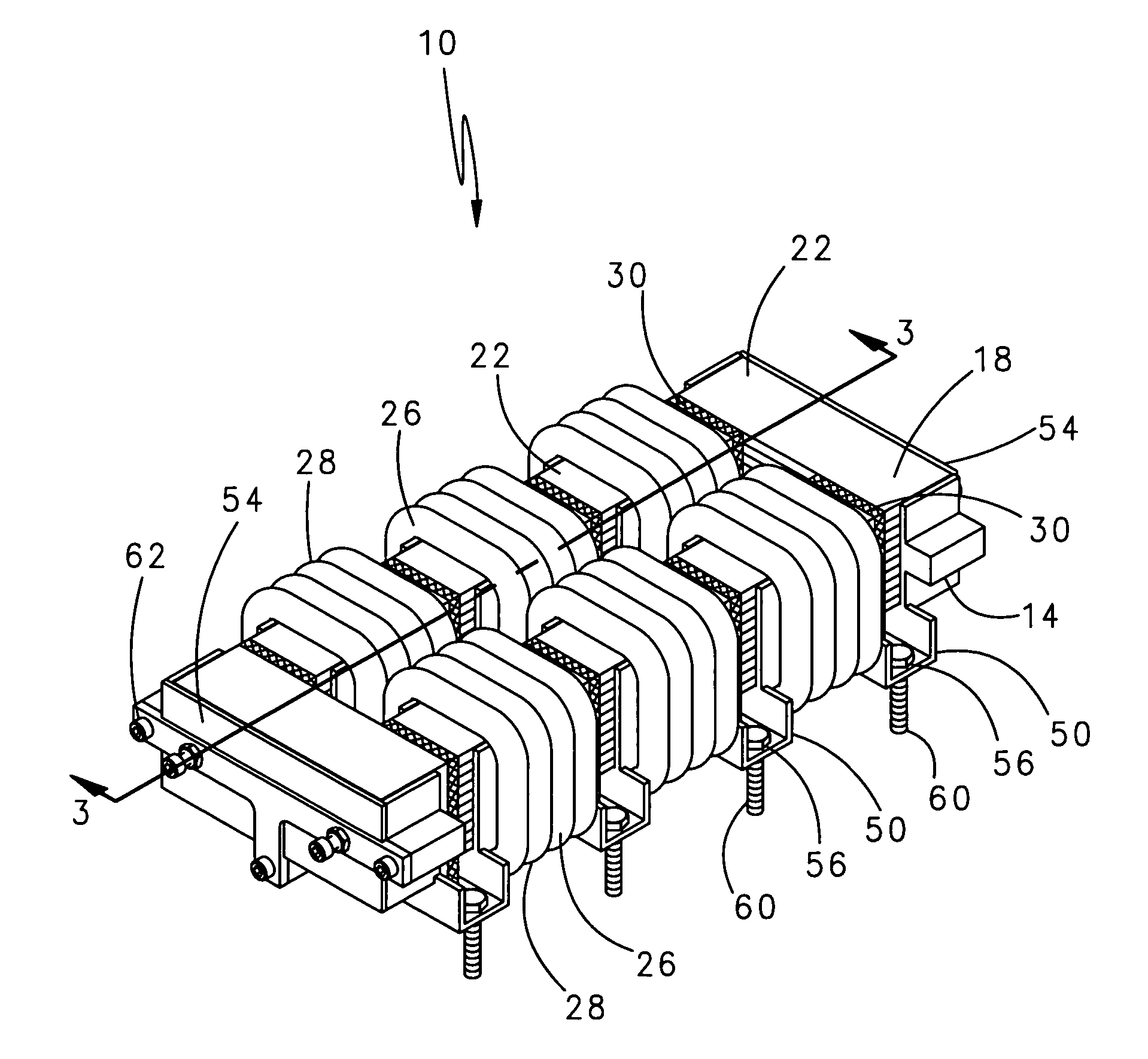
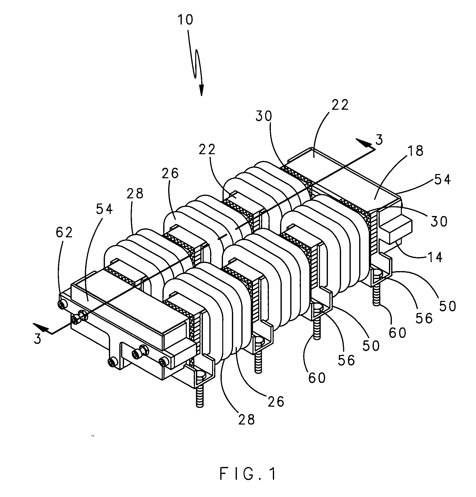
[0017]FIG. 1 illustrates an isometric view of a typical cut core inductor assembly 10 having a magnetic core 18 disposed in a winding 26. The magnetic core 18 includes a multitude of magnetic core sections 22 arranged on a mounting frame 14. The winding 26 includes a multitude of winding sections 28 each encircling a portion of one of the magnetic core sections 22 and a portion of the mounting frame 14. Multiple air gap spacers 30 separate adjacent magnetic core sections 22 of the magnetic core 18. An electric current travels through the inductor assembly 10 generating a magnetic field and thermal energy.

[0018] The inductor assembly 10 may include magnetic core sections 22 of varying sizes. For example, the inductor assembly 10 may include larger magnetic core sections 22 near the ends of the inductor assembly 10. It should be understood that although a rectangular inductor assembly 10 is described, various other geometries or arrangements of magnetic core sections 22 are included ...


PUM

PropertyMeasurementUnit
magneticaaaaaaaaaa
thermal conductiveaaaaaaaaaa
thermally conductiveaaaaaaaaaa

Abstract

A power inductor assembly includes and multiple coil sections disposed upon a mounting frame. Multiple winding sections each encircle one of the multiple core sections and a portion of the mounting frame. Air gap spacers separate adjacent core sections. The arrangement facilitates removal of thermal energy from the magnetic core. Lamination build direction normal to inductor mounting surface minimizes eddy current losses.

Description

BACKGROUND OF THE INVENTION [0001] The present invention relates generally to an inductor and, more particularly, to an inductor with multiple air gaps for thermal management. [0002] High power motor controllers typically require inductors exhibiting stable inductance at both high magnitude currents and at frequencies ranging from DC to tens of kilohertz. Parameters for one such inductor, typical of aerospace applications, operates at: 35 μH rated for 260 A at 1,400 Hz continuous. An inductor designed to these parameters should retain 90% inductance at DC currents up to 880 amps. These inductors, specifically power quality filter inductors, should be lightweight and be configured for conduction cooling. Use in aerospace applications heightens the need for lightweight inductors. [0003] Many conventional inductor permutations attempt to meet desired performance parameters yet minimize inductor weight. One such inductor is a gapped tape-wound cut core inductor. This type of inductor co...

Claims


Application Information

Patent Timeline
Patent Type & Authority Applications(United States)
IPC IPC(8): H01F27/06
CPCH01F3/14H01F27/06H01F27/245H01F27/306H01F27/346H01F37/00H01F2027/348
Inventor THIEL, CLIFFORD G.DRIESSEN, DARINPAL, DEBABRATAFENG, FRANK
Owner HAMILTON SUNDSTRAND CORP
Why Eureka
Try Eureka