Scanning laser microscope apparatus and light-amount detection unit

Inactive Publication Date: 2007-04-12
OLYMPUS CORP
View PDF5 Cites 36 Cited by
  • Summary
  • Abstract
  • Description
  • Claims
  • Application Information

AI Technical Summary

Benefits of technology

[0030] According to the light-amount detection unit described above, the light intensity of the optical stimulus laser beam irradiating the specimen is measured and the integrated value of the measured value is output. Therefore, by displaying the integrated value on a display device or the like in a device which receives the integrated val

Problems solved by technology

Therefore, even though the optical stimulus is to be quantified, quantif

Method used


Image

  • Scanning laser microscope apparatus and light-amount detection unit
  • Scanning laser microscope apparatus and light-amount detection unit
  • Scanning laser microscope apparatus and light-amount detection unit

Examples


first embodiment

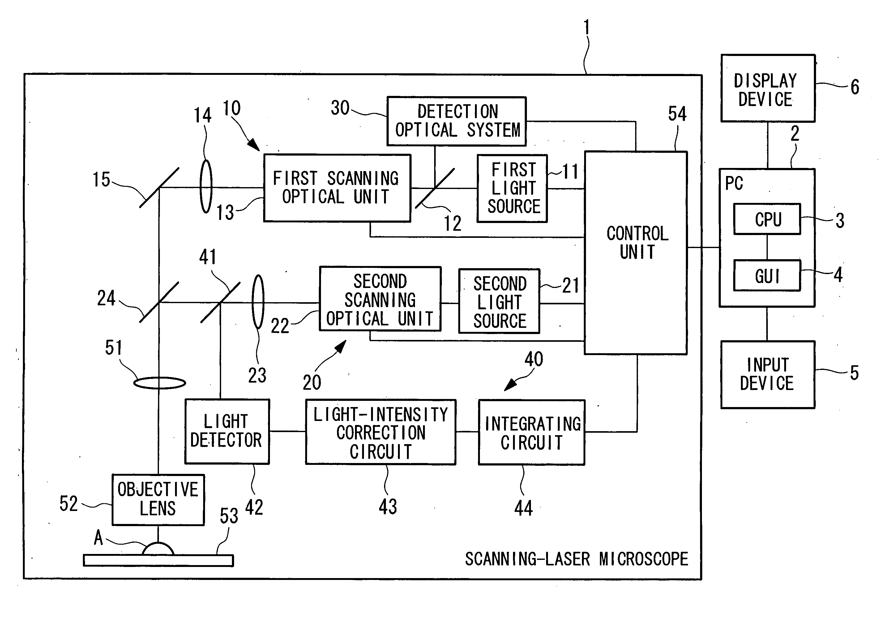
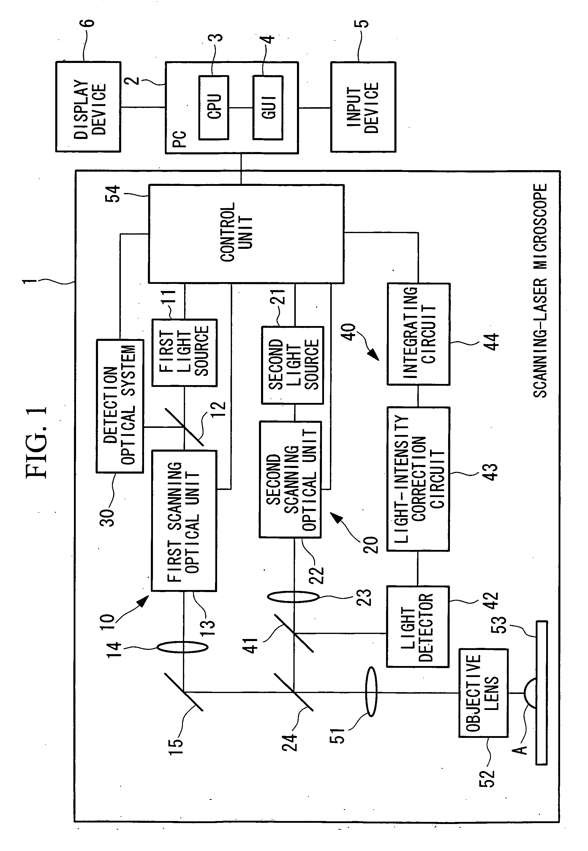
[0045]FIG. 1 is a block diagram showing, in outline, a laser microscope apparatus according to a first embodiment of the present invention.

[0046] The laser microscope apparatus according to this embodiment is formed of a scanning-laser microscope 1 and a computer 2.

[0047] The scanning-laser microscope 1 includes an image-acquisition optical system 10 for irradiating an image-acquisition laser beam while two-dimensionally scanning it on a focal plane on a specimen, a stimulus optical system 20 for irradiating the specimen with a stimulus laser beam for applying a stimulus to the specimen, a detection optical system 30 for detecting reflected light from the specimen, and a light-amount measuring apparatus 40 for measuring the light amount of the stimulus laser beam.

[0048] The image-acquisition optical system 10 is formed of a first light source 11, a dichroic mirror 12, a first scanning optical unit (first scanning optical system) 13, a relay lens 14, and a mirror 15.

[0049] The st...

second embodiment

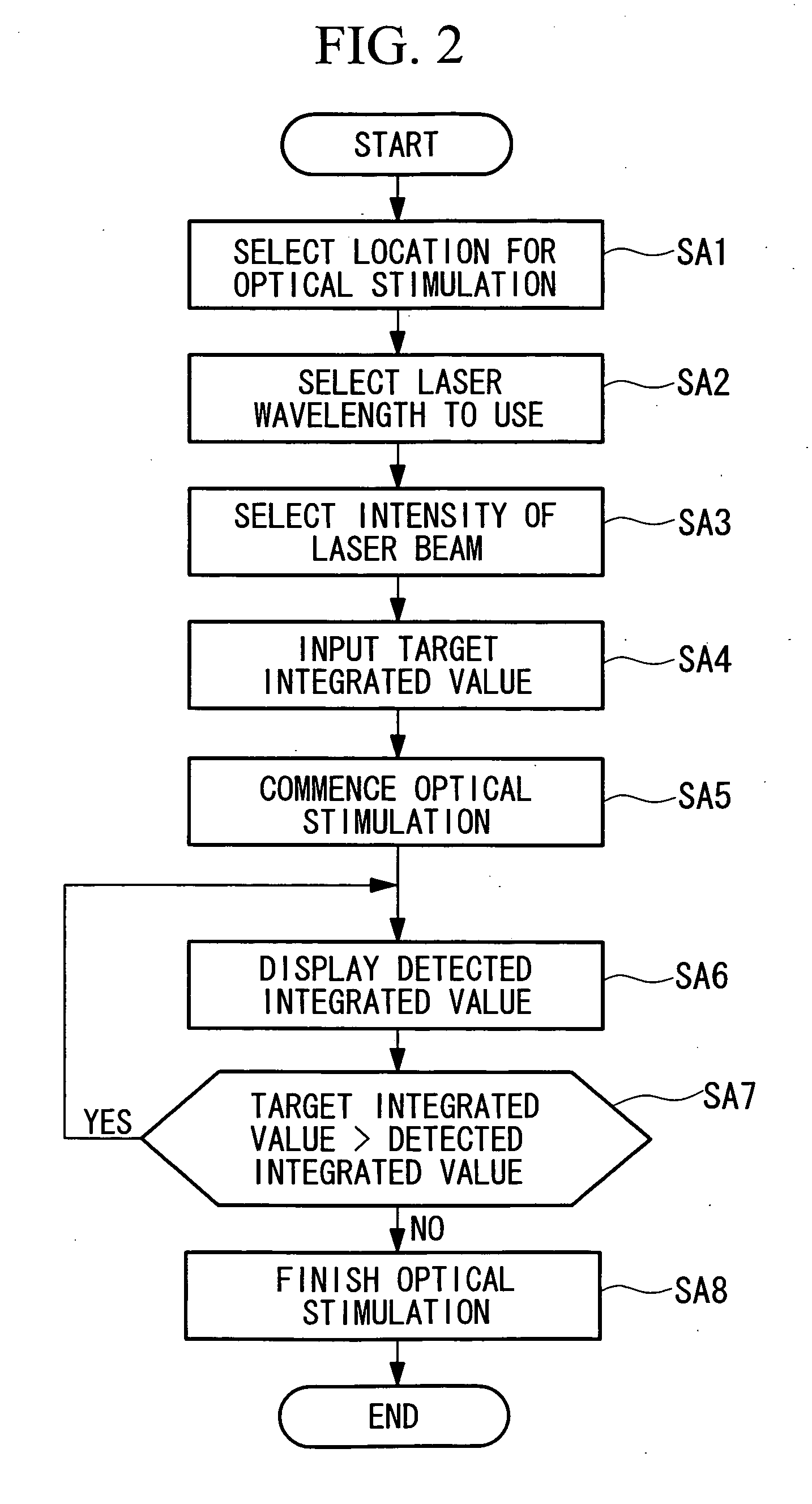
[0077] Next, a scanning-laser microscope apparatus according to a second embodiment of the present invention is described. In the first embodiment described above, the target integrated value is input for the entire irradiation region. This embodiment, however, differs from the embodiment described above in that the setting of the target integrated value is input as a value for each pixel in the irradiated region.

[0078] In the scanning-laser microscope apparatus of this embodiment, only the parts that differ from those in the first embodiment above will be described.

[0079] First, at step SB1 in FIG. 5, similarly to step SA1 shown in FIG. 2 described above, when specifying the irradiated region, the GUI 4 displays a condition-setting panel on the display of the display device 6 in step SB2. FIG. 6 shows an example of the condition-setting panel according to this embodiment. As shown in this figure, in addition to a selection switch for the type of laser (wavelength) and an input bo...

third embodiment

[0089] Next, a scanning-laser microscope according to a third embodiment of the present invention is described. In the second embodiment described above, the determination as to whether or not the detected integrated value reaches the target integrated value is carried out at each pixel. This embodiment, however, differs from the embodiment described above in that the determination as to whether or not the detected integrated value has reached the target integrated value is carried out after the stimulus laser beam is irradiated while scanning over the entire irradiation region.

[0090] For the scanning-laser microscope apparatus according to this embodiment, only the parts that are different from those in the above-mentioned second embodiment will be described below.

[0091] In step SC1 in FIG. 7, similarly to step SB1 shown in FIG. 5, when specifying the irradiation region, the GUI 4 displays a condition-setting panel on the display of the display device 6 in step SC2. FIG. 8 shows ...


PUM


Abstract

It is an object to provide a scanning-laser microscope apparatus and a light-amount detection unit that can perform quantitative observation by reporting to the operator the light intensity irradiating a specimen due to optical stimulation. There is provided a laser microscope apparatus including a stimulus optical system for irradiating a stimulus laser beam for applying a stimulus to a specific position of a specimen; a light detector for measuring the light intensity of the stimulus laser beam; a light-intensity correction circuit for correcting the measured value from the light detector; an integrating circuit for integrating the detected value from the light-intensity correction circuit; and a display device for displaying the detected integrated value from the integrating circuit.

Description

BACKGROUND OF THE INVENTION [0001] 1. Field of the Invention [0002] The present invention relates to a scanning-laser microscope apparatus which detects transmitted light or reflected light from a specimen or fluorescence generated in the specimen when the specimen is scanned with a laser beam, and more particularly, to a light-amount detection unit for detecting the amount of light applied to a specimen for optical stimulation. [0003] This application is based on Japanese Patent Application No. 2005-283023, the content of which is incorporated herein by reference. [0004] 2. Description of Related Art [0005] A scanning-laser microscope is a microscope which irradiates a specimen with a laser beam while scanning it in the X-axis and Y-axis directions and which detects, using a detector, transmitted light or reflected light from the specimen or fluorescence generated in the specimen to obtain two-dimensional intensity information of the transmitted light, reflected light, or fluoresce...

Claims


Application Information

Patent Timeline
IPC IPC(8): G02B21/06
CPCG02B21/0024G02B21/0096G02B21/16
Inventor HATTORI, TOSHIYUKI
Owner OLYMPUS CORP
Why Eureka
Try Eureka