A pulse-frequency mode dc-dc converter circuit
a converter circuit and pulse-frequency mode technology, applied in the direction of electric variable regulation, process and machine control, instruments, etc., can solve the problem of increasing the cost of building a regulator circuit using the regulator circuit, and achieve the effect of reducing gate charge dissipation and optimizing efficiency
- Summary
- Abstract
- Description
- Claims
- Application Information
AI Technical Summary
Benefits of technology
Problems solved by technology
Method used
Image
Examples
Embodiment Construction
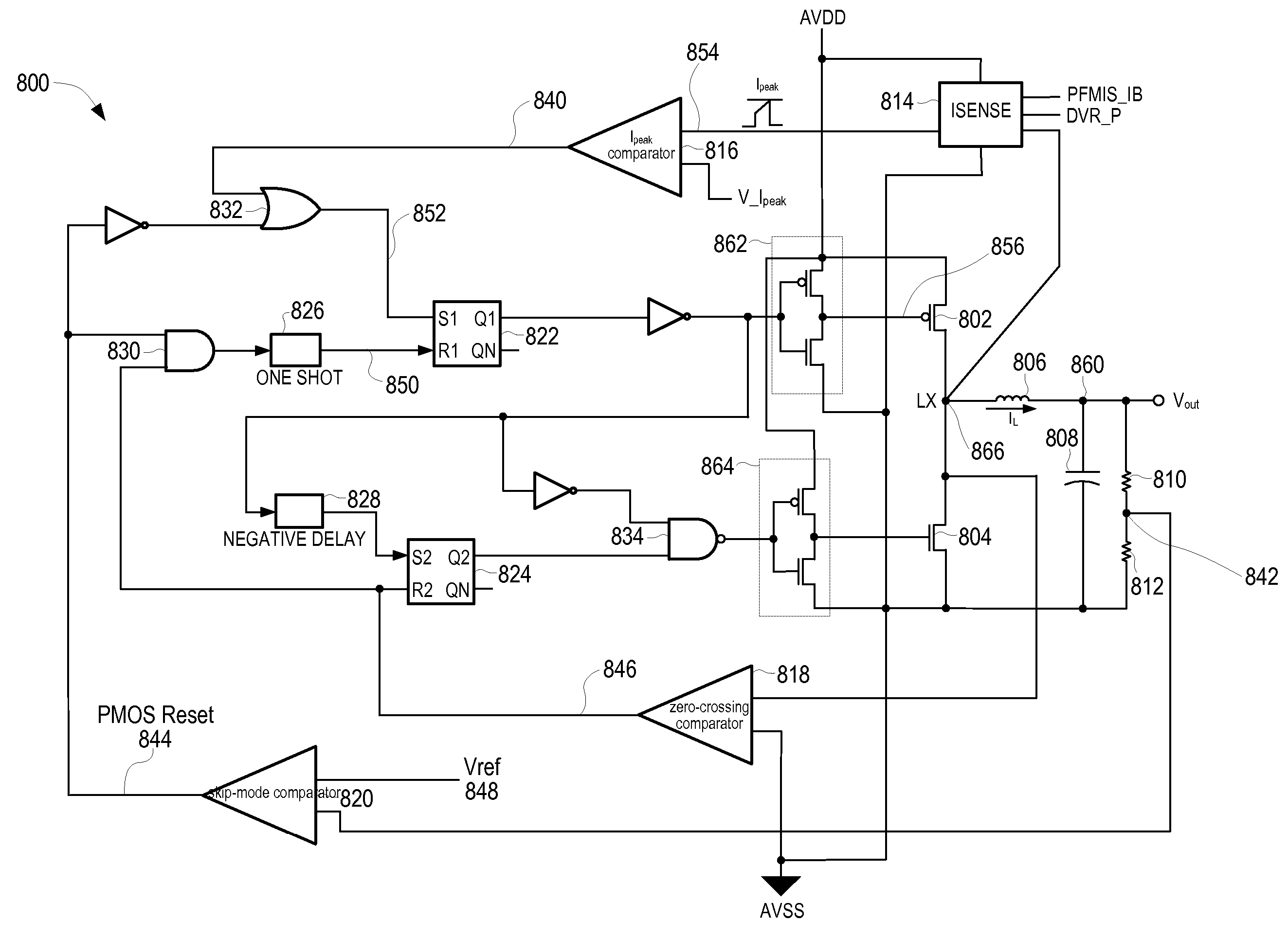
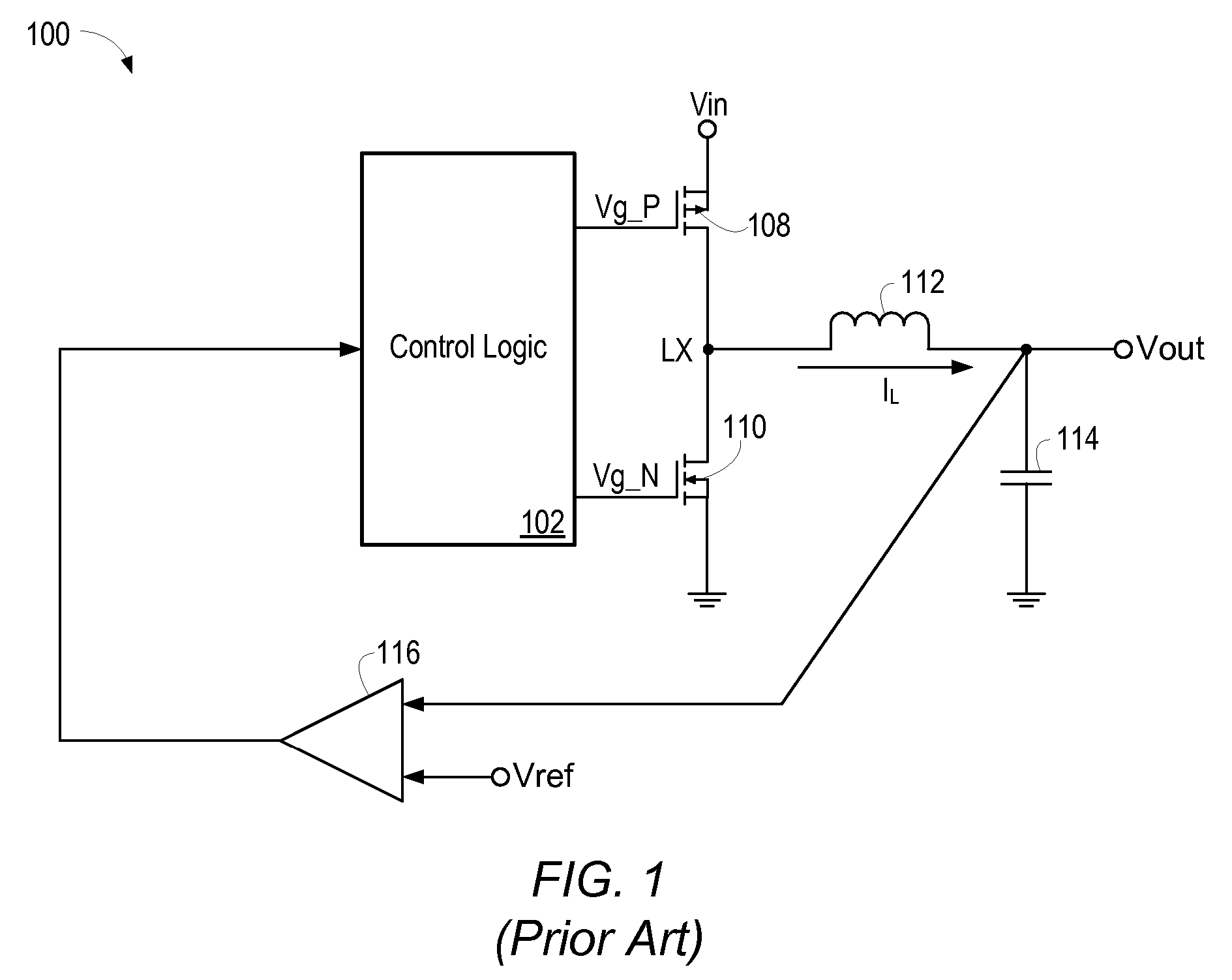
[0022] Referring again to FIG. 1, operation of a synchronous buck converter may be further examined. FIG. 3 shows voltage waveforms Vg_P 202, Vg_N 204, and Vx 206 (voltage at node LX), as well as inductor current IL 208 and corresponding load current ILoad as observed during high current load operation of synchronous buck converter 100. When Vg_P 202 is logic low, transistor 108 is turned on. When Vg_N is logic high, transistor 110 is turned on. The deadtime delay tdead indicates the time period when both transistors are turned off. As shown in FIG. 3, the average inductor current (i.e. the average of IL) is essentially equal to the DC load current provided by converter 100, indicated in FIG. 3 as ILoad. FIG. 4 shows a timing diagram of the inductor current (and correspondingly the DC load current) observed during light current load operation of converter 100. As seen in FIG. 4, when ILoad is less than half the magnitude of the peak-to-peak ripple of current IL, the entire IL wavefo...
PUM
 Abstract
Description
Claims
Application Information
 - R&D
- Intellectual Property
- Life Sciences
- Materials
- Tech Scout
- Unparalleled Data Quality
- Higher Quality Content
- 60% Fewer Hallucinations
Browse by: Latest US Patents, China's latest patents, Technical Efficacy Thesaurus, Application Domain, Technology Topic, Popular Technical Reports.
© 2025 PatSnap. All rights reserved.Legal|Privacy policy|Modern Slavery Act Transparency Statement|Sitemap|About US| Contact US: help@patsnap.com


