Dual polarization planar array antenna and cell elements therefor

a planar array and antenna technology, applied in the direction of polarised antenna unit combinations, resonant antennas, radiating element structural forms, etc., can solve the problems of interference with intra-cell isolation, inability to use antennas in applications, and inability to achieve application, so as to reduce cross coupling and increase the transmission and/or reception efficiency of antennas

Active Publication Date: 2007-04-19
PANASONIC AVIONICS CORP
View PDF83 Cites 28 Cited by
  • Summary
  • Abstract
  • Description
  • Claims
  • Application Information

AI Technical Summary

Benefits of technology

[0010] An exemplary embodiment relates to a microwave planar antenna including a plurality of radiating cells (referred to herein as radiators), having orthogonal excitation / reception probes in different layers. Each cell is surrounded by a metallic enclosure, which defines at least two different cross-sectional areas in a space between the excitation probes. In some embodiments, the different cross-sectional areas have distinctly different shapes. Alternatively or additionally, the different cross-sectional areas may differ in size. The cross sectional area of the enclosure in the space between the excitation probes may optionally be selected to allow maximal passage upwards of radiation from the lower excitation probe, while minimizing downward propagation of radiation from the upper excitation probe. Among other things, this arrangement reduces cross coupling from the upper probe downward, and increases the transmission and / or reception efficiency of the antenna.
[0012] Optionally, continuous electrical conductance is maintained along the entire height / depth of the cell enclosures, in order to improve the isolation between neighboring cells.
[0013] In some embodiments, the metallic enclosures of the cells are at least partially filled by dielectric fillers in order to lower the cutoff frequency of the cell and increase the cell's frequency response.
[0014] Optionally, several (e.g., 2-4) dielectric overlays may cover the tops of the cells in the transmission direction, to better match the cell's impedance with the open space impedance (377 ohms). This arrangement improves the radiation efficiency of the radiators and the array as a whole.

Problems solved by technology

Intra-cell isolation between the beams, however, is limited in the Rammos antenna and therefore the antenna can not be used in applications which are sensitive to signal polarization.
The problem of isolation between the beams of a single cell is compounded in relatively large planar arrays, which are used for transmissions over a relatively large bandwidth (e.g., for communications).
While such metallic frames improve the radiation efficiency of each cell, they interfere with the intra-cell isolation and make it even harder to use dual-polarization cells.

Method used


Image

  • Dual polarization planar array antenna and cell elements therefor
  • Dual polarization planar array antenna and cell elements therefor
  • Dual polarization planar array antenna and cell elements therefor

Examples


Embodiment Construction

General Structure

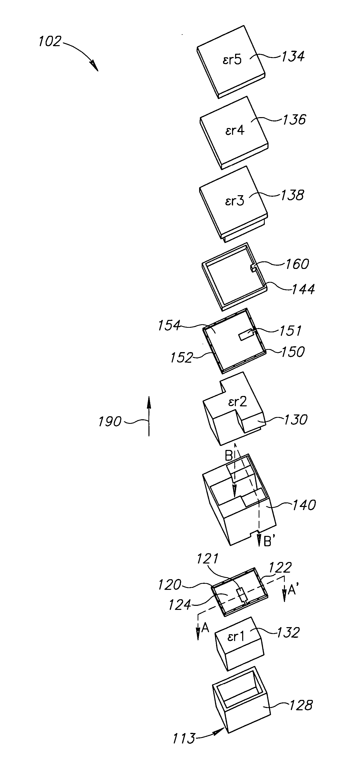
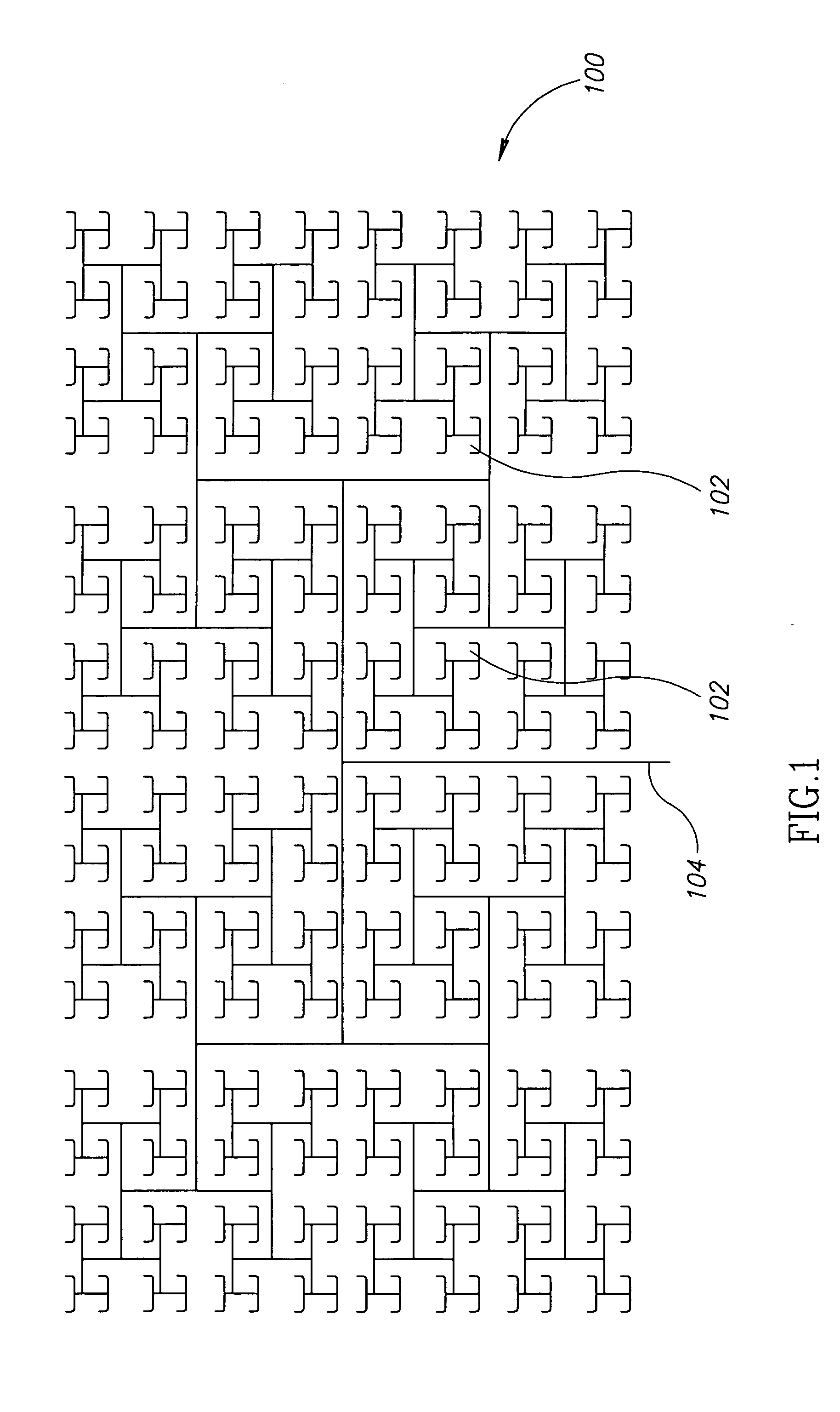
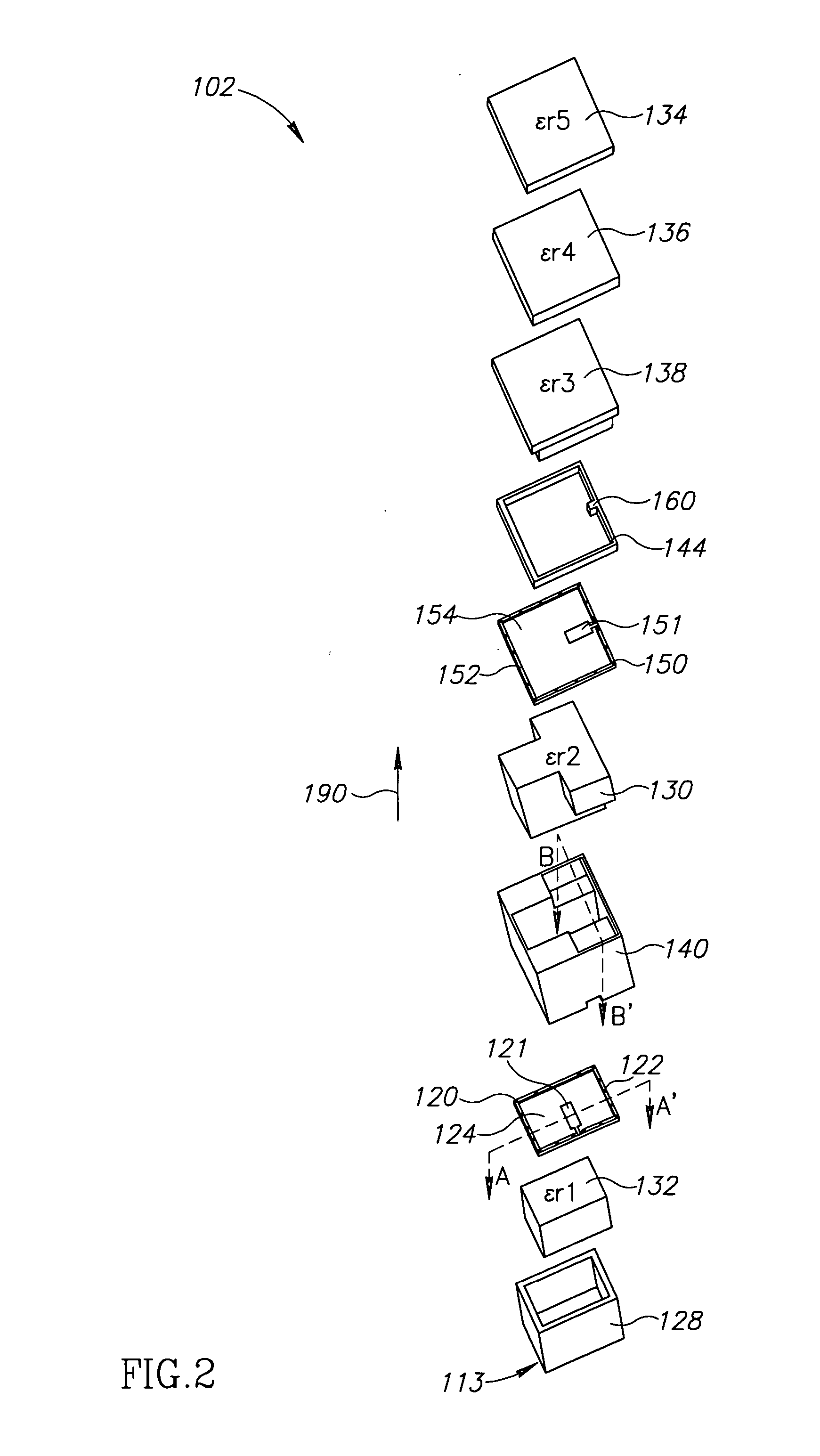
[0030]FIG. 1 is a schematic top view layout of a corporate conductive feed array for an exemplary antenna panel 100, in accordance with an exemplary embodiment. Antenna panel 100 includes a plurality of cells 102 at the distal end of each feed point which are connected in a corporate array of feed lines to a central single main feed line 104, in what is commonly referred to as a corporate feed network (CFN). Although only one CFN is shown in FIG. 1, antenna panel 100 typically includes two CFNs in two parallel layers. The CFNs are optionally separated by an isolating layer and are optionally sandwiched between isolating layers. Optionally, the CFN may be realized with micro-strip lines, suspended strip lines and / or waveguides, although other physical structures for RF transmission lines may be used.

[0031] In some embodiments, antenna panel 100 includes at least 16, 20 or even at least 50 (e.g., 64) cells. Optionally, antenna panel 100 includes at least 100, 250 o...


PUM


Abstract

An RF antenna structure (e.g., a planar array) includes at least one radiation cell (and typically many, e.g., 16 or 32 or 64, etc.) having a conductive enclosure and an upper probe and a lower probe located at different heights within the enclosure. The enclosure between the upper probe and a bottom of the cell has at least two different cross-sectional areas. The upper and lower probes are preferably oriented at substantially 90° relative to each other. An upper portion of the enclosure beneath the upper probe may have a larger dimension than a lower portion such that the upper portion allows propagation of waves generated by the upper probe in a predetermined frequency band while the lower portion (e.g., above the lower probe) does not substantially allow propagation of waves generated by the upper probe, in the predetermined frequency band.

Description

BACKGROUND [0001] 1. Technical Field [0002] The present invention relates to antennas and particularly to cavity backed antennas. [0003] 2. Related Art [0004] One type of antenna suitable, for example, for satellite communication is planar array antennas. Planar array antennas are generally formed of an array of many (e.g., hundreds) cells, defined at least in part on printed circuit boards. [0005] In a simple antenna, each cell includes a single electric probe, which either receives electromagnetic signals from a remote antenna (e.g., a satellite carried antenna) or transmits electromagnetic signals toward a remote antenna. A bottom reflective layer of the planar antenna reflects electromagnetic signals propagating downward, such that they reflect upwards toward the remote antenna. [0006] It has been suggested to use a dual beam and dual polarization antenna, in which each cell includes two orthogonal electric probes, in separate layers, such that the probes share a common cell ape...

Claims


Application Information

Patent Timeline
Patent Type & Authority Applications(United States)
IPC IPC(8): H01Q1/38H01Q9/28
CPCH01Q21/064H01Q21/24
Inventor ENGEL, BENJAMIN M.
Owner PANASONIC AVIONICS CORP
Why Eureka
Try Eureka