Acoustic galvanic isolator incorporating series-connected decoupled stacked bulk acoustic resonators

Inactive Publication Date: 2007-04-19
AVAGO TECH INT SALES PTE LTD
View PDF99 Cites 89 Cited by
  • Summary
  • Abstract
  • Description
  • Claims
  • Application Information

AI Technical Summary

Benefits of technology

[0009] An electrically-isolating acoustic coupler comprising series-connected decoupled stacked bulk acoustic resonators (DSBARs) is physically small and is inexpensive to fabricate yet

Problems solved by technology

Inexpensive opto-isolators are typically limited to data rates of about 10 Mb/s by device capacitance, and from power limitations of the optical devices.
Such conflicting requiremen

Method used


Image

  • Acoustic galvanic isolator incorporating series-connected decoupled stacked bulk acoustic resonators
  • Acoustic galvanic isolator incorporating series-connected decoupled stacked bulk acoustic resonators
  • Acoustic galvanic isolator incorporating series-connected decoupled stacked bulk acoustic resonators

Examples


first embodiment

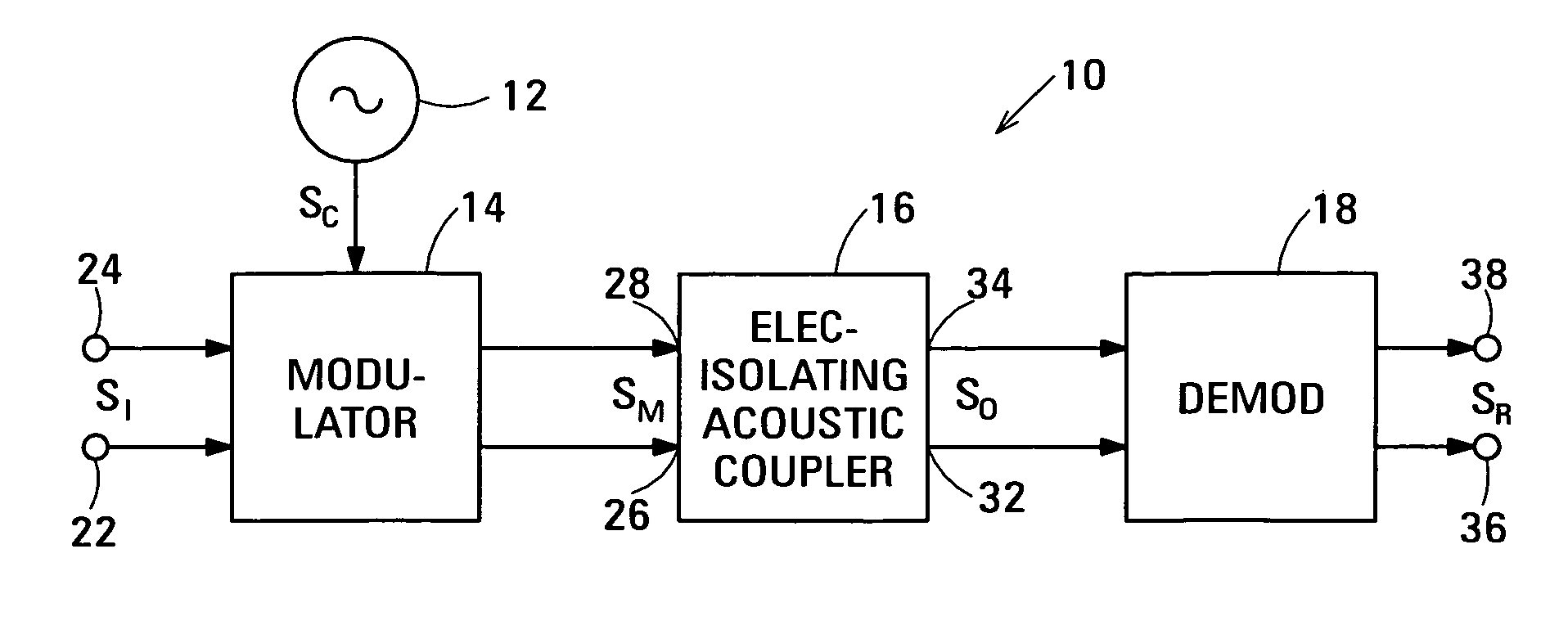
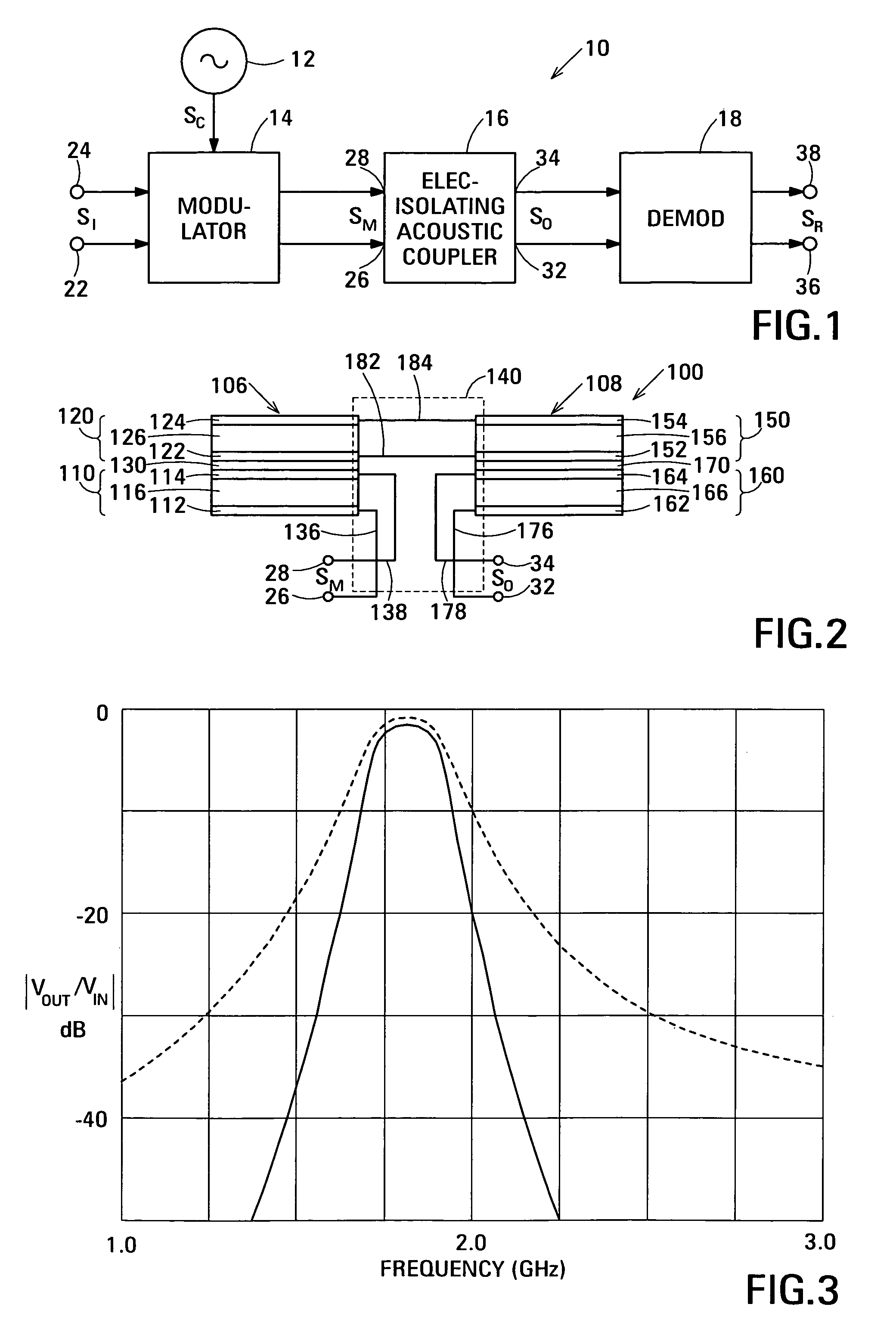
[0027]FIG. 1 is a block diagram showing an acoustic galvanic isolator 10 in accordance with the invention. Acoustic galvanic isolator 10 transmits an electrical information signal SI between its input terminals and its output terminals yet provides electrical isolation between its input terminals and its output terminals. Acoustic galvanic isolator 10 not only provides electrical isolation at DC but also provides a.c. electrical isolation. Electrical information signal SI is typically a high data rate digital data signal, but may alternatively be an analog signal. In one application, electrical information signal SI is a 100 Mbit / sec Ethernet signal.

[0028] In the example shown, acoustic galvanic isolator 10 is composed of a local oscillator 12, a modulator 14, an electrically-isolating acoustic coupler 16 and a demodulator 18. In the example shown, local oscillator 12 is the source of an electrical carrier signal SC. Modulator 14 has an input connected to receive electrical informat...

second embodiment

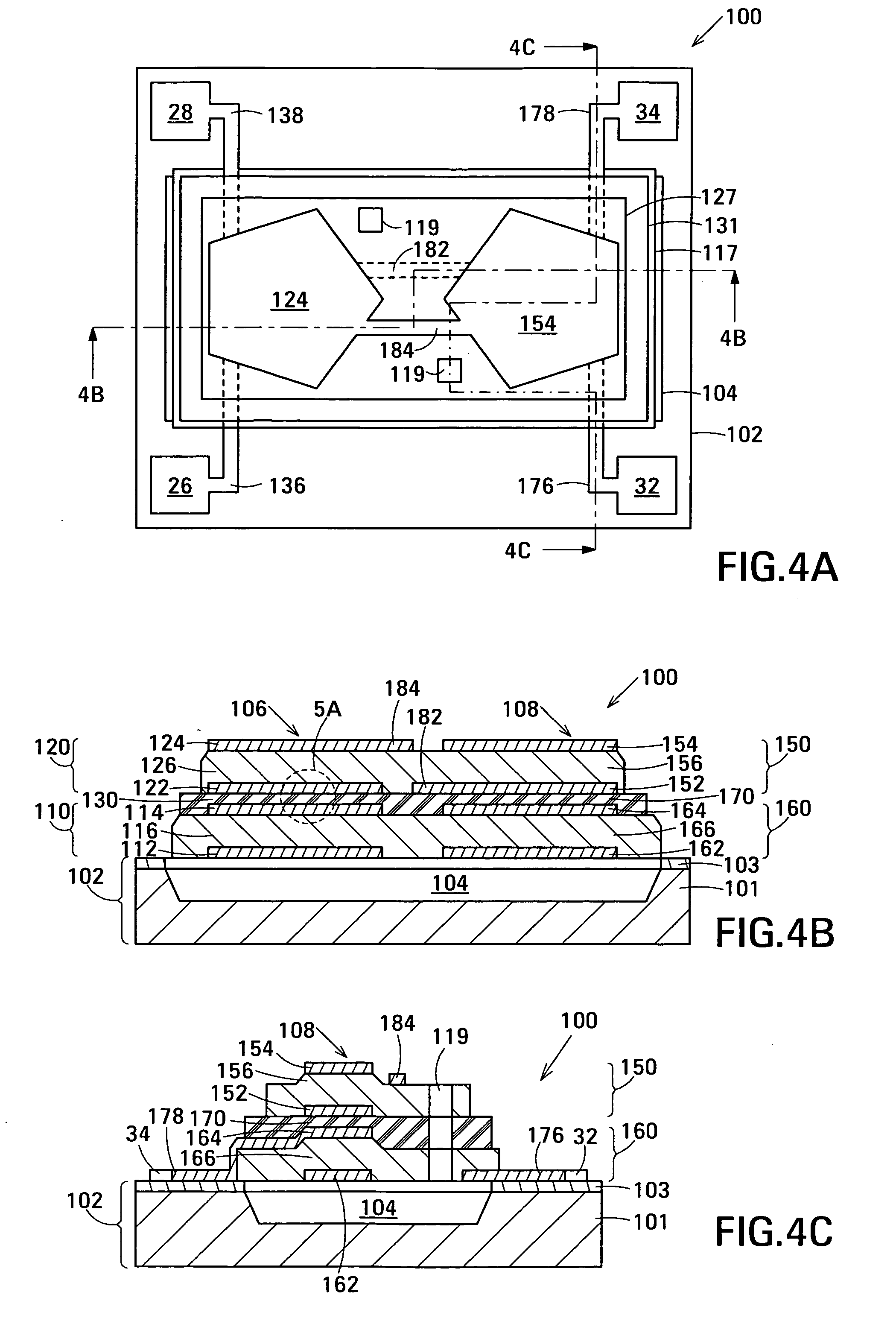
[0070]FIG. 5B is an enlarged view of the portion marked 5A in FIG. 4B showing electrically-insulating acoustic decoupler 130. Electrically-insulating acoustic coupler 170 can be similarly structured. The following description of acoustic decoupler 130 also applies to acoustic decoupler 170. Consequently, acoustic decoupler 170 will not be separately described. In the embodiment shown in FIG. 5B, acoustic decoupler 130 is composed of an electrically-insulating acoustic Bragg structure 161 located between electrode 114 of FBAR 110 and electrode 122 of FBAR 120. Acoustic Bragg structure 161 comprises a low acoustic impedance Bragg element 163 located between high acoustic impedance Bragg elements 165 and 167. At least one of the Bragg elements comprises a layer of material having a high electrical resistivity, a low dielectric permittivity and a high breakdown field.

[0071] Each of the Bragg elements 163, 165 and 167 is a quarter-wave layer. Low acoustic impedance Bragg element 163 is a...

third embodiment

[0092]FIG. 8 is a schematic diagram showing an example of an acoustic coupler 300 in accordance with the invention. FIG. 9A is a plan view showing a practical example of acoustic coupler 300. FIGS. 9B and 9C are cross-sectional views along section lines 9B-9B and 9C-9C, respectively, shown in FIG. 9A. The same reference numerals are used to denote the elements of acoustic coupler 300 in FIG. 8 and in FIGS. 9A-9C.

[0093] Acoustic coupler 300 comprises inputs 26, 28, outputs 32, 34, an insulated decoupled stacked bulk acoustic resonator (IDSBAR) 306, an IDSBAR 308 and electrical circuit 140 that connects IDSBARs 306 and 308 in series between the inputs and the outputs. In acoustic decoupler 300, each of IDSBARs 306 and 308 is an IDSBAR in accordance with a second IDSBAR embodiment. In its simplest form, an IDSBAR in accordance with the second IDSBAR embodiment has a first half-wave acoustically-resonant electrical insulator, an acoustic decoupler and a second half-wave acoustically-res...


PUM


Abstract

Embodiments of the acoustic galvanic isolator comprise a carrier signal source, a modulator connected to receive an information signal and the carrier signal, a demodulator, and an electrically-isolating acoustic coupler connected between the modulator and the demodulator. The electrically-isolating acoustic coupler comprises series-connected decoupled stacked bulk acoustic resonators (DSBARs).

Description

RELATED APPLICATIONS [0001] This disclosure is related to the following simultaneously-filed disclosures: Acoustic Galvanic Isolator Incorporating Single Decoupled Stacked Bulk Acoustic Resonator of John D. Larson III (Agilent Docket No. 10051180-1); Acoustic Galvanic Isolator Incorporating Single Insulated Decoupled Stacked Bulk Acoustic Resonator With Acoustically-Resonant Electrical Insulator of John D. Larson III (Agilent Docket No. 10051205-1); Acoustic Galvanic Isolator Incorporating Film Acoustically-Coupled Transformer of John D. Larson III et al. (Agilent Docket No. 10051206-1); and Acoustic Galvanic Isolator of John D. Larson III et al. (Agilent Docket No. 10051583-1), all of which are assigned to the assignee of this disclosure and are incorporated by reference.BACKGROUND [0002] A galvanic isolator allows an information signal to pass from its input to its output but has no electrical conduction path between its input and its output. The lack of an electrical conduction p...

Claims


Application Information

Patent Timeline
IPC IPC(8): H01S3/00
CPCH03H9/132H03H9/584H03H9/587H03H9/60H03H9/02007H03H9/171
Inventor LARSON, JOHN D. IIIHARDCASTLE, IAN
Owner AVAGO TECH INT SALES PTE LTD
Why Eureka
Try Eureka