Low stress STI films and methods

a technology of low stress and sti, applied in the field of low stress sti films and methods, can solve the problems of difficult to fill spaces using conventional methods, increased aspect ratio gaps in some applications, and fsg films, and achieve low compressive stress, good gap filling characteristics, and low compressive stress

Inactive Publication Date: 2007-04-19
APPLIED MATERIALS INC
View PDF6 Cites 110 Cited by
  • Summary
  • Abstract
  • Description
  • Claims
  • Application Information

AI Technical Summary

Benefits of technology

[0010] The present invention generally relates to low compressive stress doped silicate glass films for STI applications. By way of non-limited example, the stress-lowering dopant may be a fluorine dopant, a germanium dopant, or a phosphorous dopant. The low compressive stress STI films will generally exhibit a compressive stress of less than 180 MPa, and preferably less than about 170 MPa. In certain embodiment, the STI films of the invention will exhibit a compressive stress less than about 100 MPa. Further, in certain embodiments, the low compressive stress STI films of the invention will comprise between about 0.1 and 25 atomic % of the stress-lowering dopant.
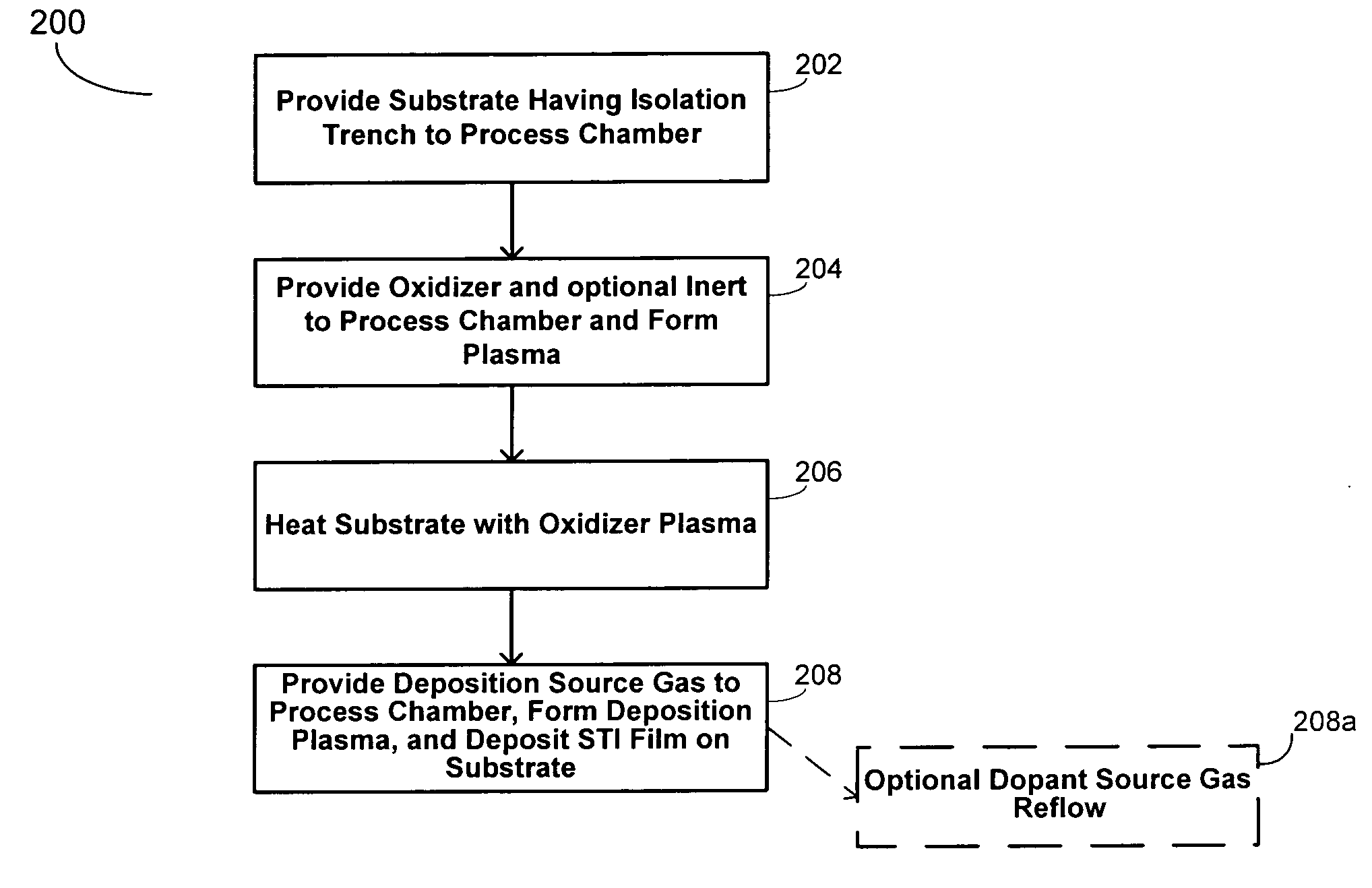
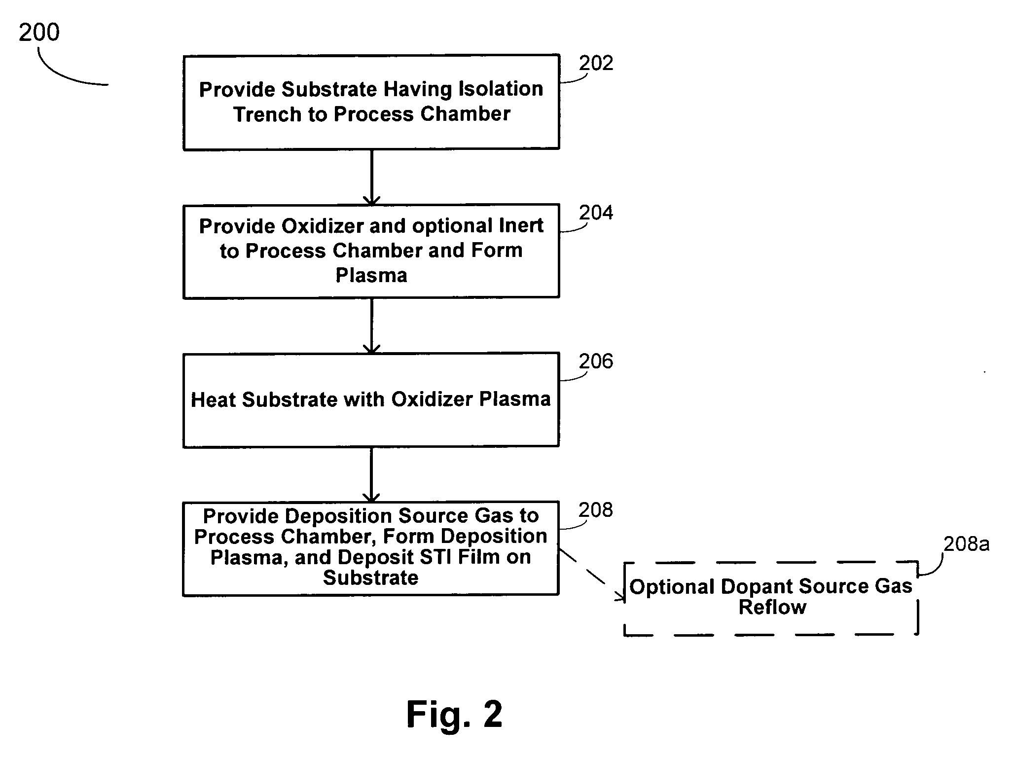
[0011] In one aspect, the invention provides a method of depositing a low compressive stress, shallow trench isolation (STI) film with good gap fill characteristics on a substrate having a gap between adjacent raised surfaces. The method generally comprises: (a) positioning the substrate in a deposition chamber; (b) providing a gas mixture to the deposition chamber in one or more steps; (c) reacting the gas mixture in the presence of an electric field to generate a plasma having an ion density of at least 1011 ions/cm3; (d) and exposing the substrate to the plasma under conditions sufficient to thereby deposit a low compressive stress STI film within the gap of the substrate. In accordance with such a method, the gas mixture pre

Problems solved by technology

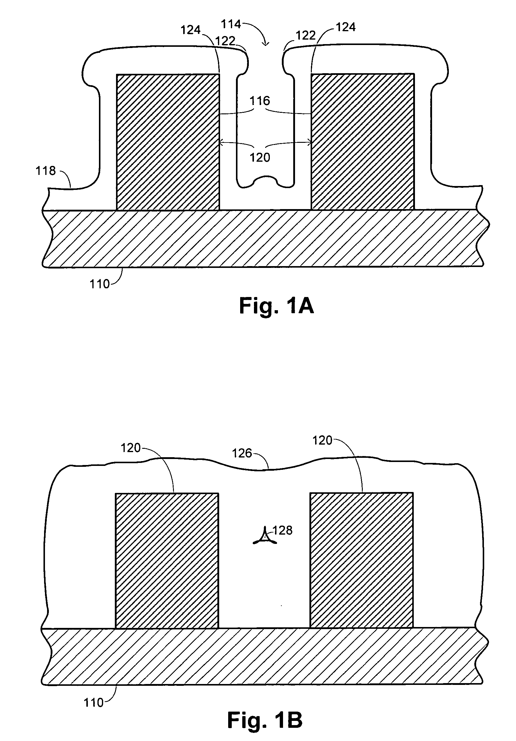
Smaller feature sizes have resulted in the presence of increased aspect ratio gaps for some applications, for example, between adjacent conductive lines or in etched trenches.
These spaces are difficult to fill using conventional methods.
Because of stability and other issues, FSG films are generally not used for PMD or STI applications and have been primarily limited to i

Method used


Image

  • Low stress STI films and methods
  • Low stress STI films and methods
  • Low stress STI films and methods

Examples


Embodiment Construction

I. Introduction

[0019] The present invention generally relates to low compressive stress doped silicate glass for STI application. By way of non-limiting example, the compressive stress lowering dopant may be fluorine, germanium, or phosphorous.

[0020] In one embodiment, fluorine may be incorporated into silicate glass to result in low stress STI films (e.g., an in-situ etch assisted (ISEA) deposited film, ˜180 MPa). Previous FSG processes utilizing fluorine typically result in an MM film having a compressive stress of approximately <80 MPa. However, in accordance with the present invention, it has been discovered that higher fluorine levels may be incorporated into STI films to thereby further reduce the compressive stress of the resultant film to levels below 180 MPa (e.g., below about 170 MPa, 150 MPa, 100 MPa, 90 MPa, 70 MPa, etc.) with good gap fill capabilities. The present invention combines the advantages of ISEA deposition and FSG films to obtain higher fluorine levels at hi...


PUM

PropertyMeasurementUnit
Temperatureaaaaaaaaaa
Pressureaaaaaaaaaa
Poweraaaaaaaaaa

Abstract

The present invention generally relates to low compressive stress doped silicate glass films for STI applications. By way of non-limited example, the stress-lowering dopant may be a fluorine dopant, a germanium dopant, or a phosphorous dopant. The low compressive stress STI films will generally exhibit a compressive stress of less than 180 MPa, and preferably less than about 170 MPa. In certain embodiment, the STI films of the invention will exhibit a compressive stress less than about 100 MPa. Further, in certain embodiments, the low compressive stress STI films of the invention will comprise between about 0.1 and 25 atomic % of the stress-lowering dopant.

Description

BACKGROUND OF THE INVENTION [0001] Semiconductor device geometries have dramatically decreased in size since such devices were first introduced several decades ago. Smaller feature sizes have resulted in the presence of increased aspect ratio gaps for some applications, for example, between adjacent conductive lines or in etched trenches. The aspect ratio of a gap is defined by the ratio of the gap's height or depth to its width. These spaces are difficult to fill using conventional methods. A film's ability to completely fill such gaps is referred to as the film's “gap-filling” ability. Silicon oxide is one type of insulation film that is commonly used to fill the gaps in intermetal dielectric (IMD) applications, premetal dielectric (PMD) applications and shallow trench isolation (STI) applications among others. Such a silicon oxide film is often referred to as a gap-fill film or a gap-fill layer. [0002] Some integrated circuit manufacturers have turned to the use of high density p...

Claims


Application Information

Patent Timeline
IPC IPC(8): H01L21/76
CPCC23C16/045C23C16/401H01L21/02126H01L21/02129H01L21/02131H01L21/02274H01L21/31625H01L21/31629H01L21/76224
Inventor YIEH, ELLIEYHAN, LUNG-TIENWANG, ANCHUANZHANG, LIN
Owner APPLIED MATERIALS INC
Why Eureka
Try Eureka