System and method for integrated circuit timing analysis

a timing analysis and integrated circuit technology, applied in the field of integrated circuit timing analysis, can solve the problems of affecting wiring, unable to completely control physical variations, and circuit designers devote many hours to achieve the intended circuit performance, and achieve the effect of not reducing the accuracy of timing analysis of an integrated circui

Inactive Publication Date: 2007-04-19
PANASONIC CORP
View PDF2 Cites 17 Cited by
  • Summary
  • Abstract
  • Description
  • Claims
  • Application Information

AI Technical Summary

Benefits of technology

[0014] To solve the above-described problems, an object of the present invention is to achieve a timing analysis system and method which m...

Problems solved by technology

The most important issue for integrated circuit (IC) design is always timing verification.
Circuit designers devote many hours to achieve intended circuit performance.
Specifically, it is impossible to completely control physical variations, such as variations in gate length, gate width and thickness of oxide films of the transistors through the production steps.
Moreover, if metal layers and interlayer insulating films vary in thickness, wiring is affected.
Therefore, such variations lead to variations in wiring delay, as well as in gate delay.
The environmental variations also occur inevitably and cannot be avoided.
In the conventional timing verification, however, a huge number of paths must be analyzed because the numbe...

Method used


Image

  • System and method for integrated circuit timing analysis
  • System and method for integrated circuit timing analysis
  • System and method for integrated circuit timing analysis

Examples


first embodiment

MODIFICATION OF FIRST EMBODIMENT

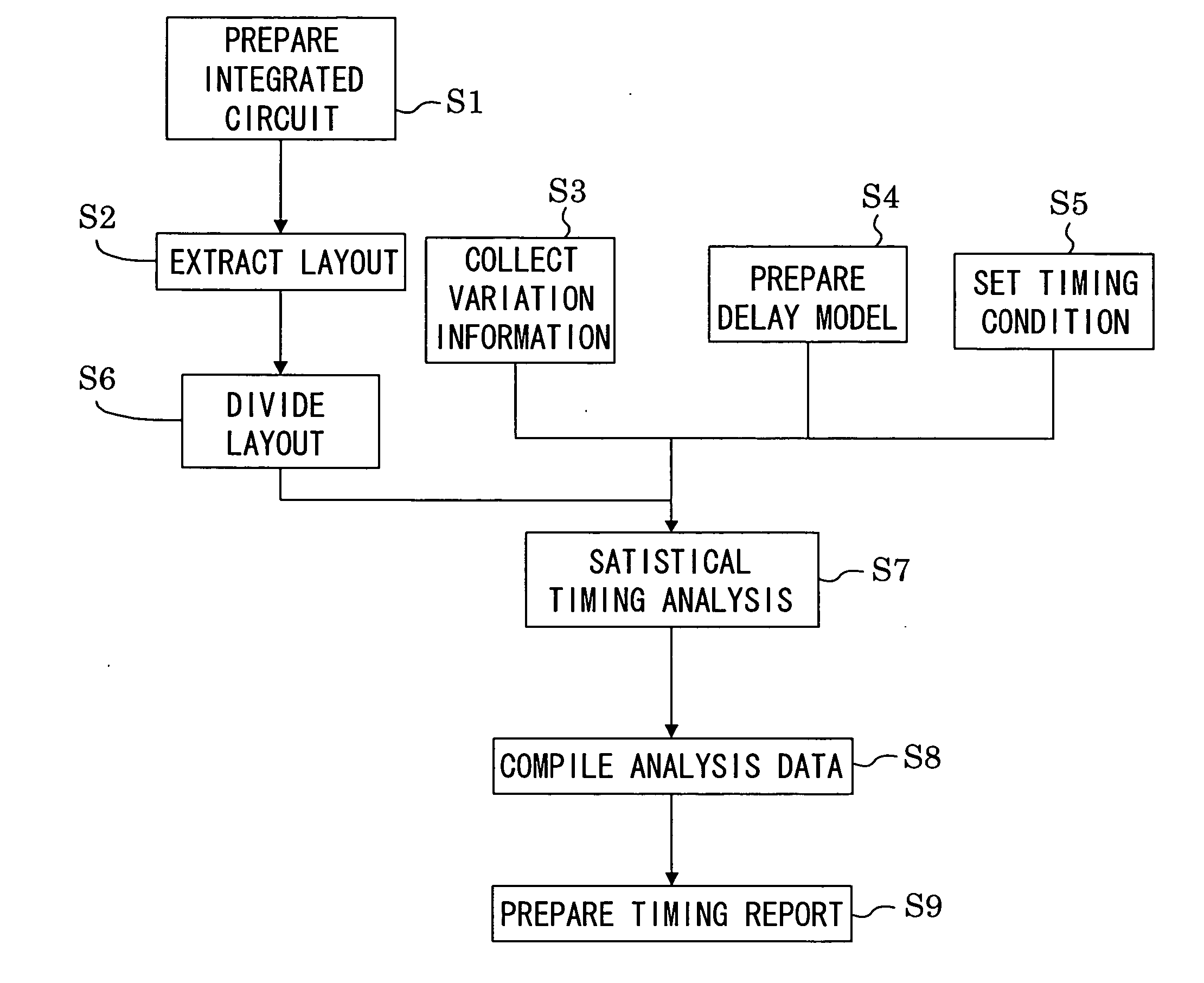
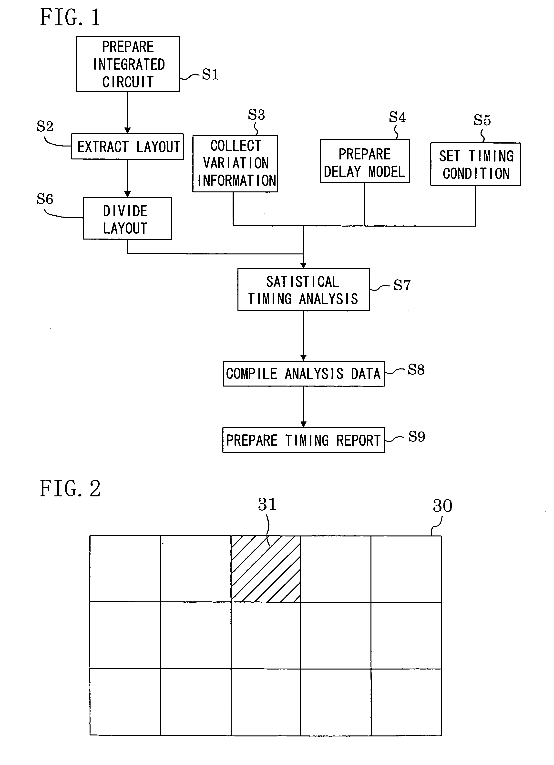
[0073] Hereinafter, a modification of the first embodiment will be explained with reference to the drawings. FIG. 5 is a flowchart illustrating a modified method for integrated circuit timing analysis. The modified timing analysis method is different from the timing analysis method of the first embodiment in that step S7 includes substep S7a for performing statistical timing analysis on each of the divided sublayouts and substep S7b for performing interpolation calculation of the boundary regions between the sublayouts. Other steps than step S7 are not explained below because they are the same as those of the first embodiment.

[0074] In the timing analysis performed on each of the sublayouts, information about connection between boundary regions of the sublayouts and the sublayouts adjacent thereto is lacking. Therefore, error occurs in the analysis results. To eliminate the error, another timing analysis is performed on the boundary regions to perfor...

second embodiment

[0079] Hereinafter, an explanation of a second embodiment of the present invention will be provided with reference to the drawings. FIG. 8 shows a flowchart illustrating a method for integrated circuit timing analysis according to the present embodiment. Other steps than step S7 shown in FIG. 8 are not explained below because they are the same as those of the first embodiment.

[0080] In the timing analysis method of the present embodiment, step S7 for performing statistical timing analysis includes substep S7c for performing preliminary timing analysis, substep S7d for extracting a critical path and substep S7e for performing statistical timing analysis on the critical path.

[0081] In substep S7c, preliminary timing analysis is performed on each of the sublayouts under a predetermined standard condition.

[0082] Then, in substep S7d, sublayouts showing critical timing are identified based on the results of the preliminary timing analysis. FIG. 9 shows the identified sublayouts showin...


PUM


Abstract

An integrated circuit timing analysis system includes: a first storage section for storing a layout of an integrated circuit including a plurality of transistors; and a processing section for processing the layout stored in the first storage section. The processing section includes a layout dividing section for dividing the layout stored in the first storage section into a plurality of sublayouts, a timing analysis section for performing statistical timing analysis on each of the sublayouts and a data compilation section for compiling the analysis data of the sublayouts to determine a timing of the integrated circuit.

Description

CROSS-REFERENCE TO RELATED APPLICATION [0001] This non-provisional application claims priority under 35 U.S.C. §119(a) of Japanese Patent Application No. 2005-301442 filed in Japan on Oct. 17, 2005, the entire contents of which are hereby incorporated by reference.BACKGROUND OF THE INVENTION [0002] 1. Field of the Invention [0003] The present invention relates to a system and method for integrated circuit timing analysis. In particular, it relates to a system and method for statistical static timing analysis taking delay variation statistics into account. [0004] 2. Description of Related Art [0005] The most important issue for integrated circuit (IC) design is always timing verification. Circuit designers devote many hours to achieve intended circuit performance. So far, various automatic design environments have been proposed to reduce the hours and enhance the efficiency of timing analysis. Examples thereof include electronic design automation (EDA) tools, such as PrimeTime by Syn...

Claims


Application Information

Patent Timeline
IPC IPC(8): G06F17/50
CPCG06F17/5031G06F30/3312
Inventor SUMIKAWA, TAKASHI
Owner PANASONIC CORP
Why Eureka
Try Eureka