Method for producing an optical element

a technology of optical elements and optical elements, applied in the field of optical element production, can solve the problems of insufficient optical performance of optical elements, additional problems in terms of highly skilled work, and substantial difficulty in final alignment, and achieve the effects of sufficient bonding strength, sufficient optical performance, and preventing separation at bonded portions

Inactive Publication Date: 2007-04-26
ASAHI GLASS CO LTD
View PDF4 Cites 47 Cited by
  • Summary
  • Abstract
  • Description
  • Claims
  • Application Information

AI Technical Summary

Benefits of technology

[0012] It is an object of the present invention to provide a method for producing an optical element by bonding a plurality of optical member with an adhesive, which is capable of providing the optical element with sufficient optical performance and with such a sufficient bonding strength to prevent separation from being made at bonded portions, and of making alignment easily.

Problems solved by technology

Although the method proposed by Patent Document 1 is suited for final alignment of optical members, which have been aligned to some extent, it is substantially difficult to make final alignment unless rough alignment (hereinbelow, referred to as initial alignment) has been made at the time of bonding.
An additional problem has arisen in terms of highly skilled work being needed to make even initial alignment.
On the other hand, if a surface to apply the above-mentioned adhesive thereon (hereinbelow, referred to as bonded surface) is poorly cleaned, there is the possibility that an optical element fails to exhibit sufficient optical performance since the adhesive involves bubbles at the time of bonding, or there is the possibility that separation is made since the bonding strength of the bonded surface is not sufficient.
Even in a case where the bonded surface can be sufficiently cleaned, if the initial alignment needs a long time because of being difficult to be simply made, there is the possibility that the cleaned surface is contaminated again during the initial alignment.
This means that additional equipment for preventing contaminations is needed and that it is impossible to increase productivity since the initial alignment requires a lot of skill.

Method used


Image

  • Method for producing an optical element
  • Method for producing an optical element
  • Method for producing an optical element

Examples


example

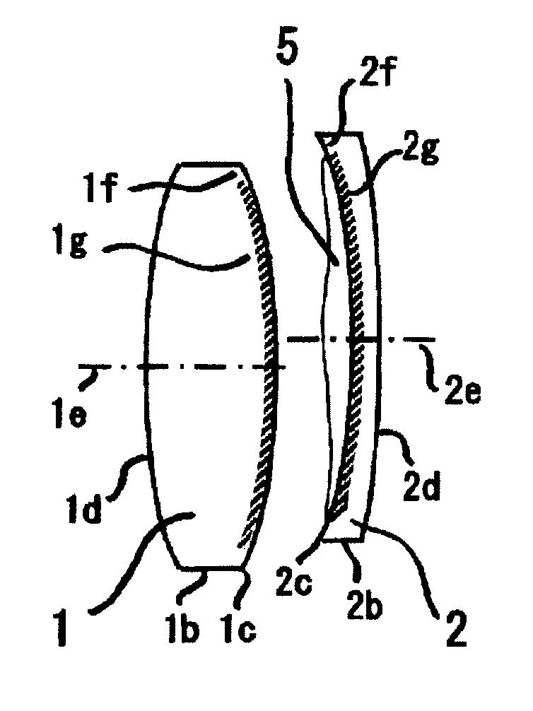
[0076] In an example of the present invention, a cemented glass lens, which had an outer diameter of 10 mm and a total thickness of 5 mm, was produced so as to be capable of eliminating chromatic aberration with respect to different wavelengths. The cemented glass lens was configured so that the concave lens 2 was made of flint glass SF2, the convex lens 1 was made of crown glass BK7, and an acrylic, ultraviolet-curable adhesive was used as the liquid adhesive 5. The convex lens 1 and the concave lens 2 both had an outer diameter of 10 mm.

[0077] As the pretreatment for dry cleaning, a nitrogen gas was blown to the convex lens 1 and the concave lens 2 as the cemented lens parts to remove dust and dirt on the bonded surfaces. Then, the convex lens and the concave lens were subjected to ultrasonic cleaning, being immersed in 1) a cleaning liquid comprising a mild detergent, 2) a cleaning liquid comprising pure water, 3) a cleaning liquid comprising isopropyl alcohol, and 4) a cleaning...


PUM

PropertyMeasurementUnit
speedaaaaaaaaaa
total thicknessaaaaaaaaaa
outer diameteraaaaaaaaaa

Abstract

A method for producing an optical element by bonding a plurality of optical member with an adhesive, which is capable of providing the optical element with sufficient optical performance and with such a sufficient bonding strength to prevent separation from being made at bonded portions, and of making alignment easily, is provided. The method for producing an optical element, which comprises bonding two or more optical members with an adhesive, is characterized in that at least one of confronting bonded surfaces on at least one pair of contact surfaces of the optical members is subjected to dry cleaning in such a state that at least a surface connecting to a bonded surface is masked, followed by applying a liquid adhesive as the adhesive on the cleaned surface and curing the liquid adhesive to bond the optical members.

Description

BACKGROUND OF THE INVENTION [0001] 1. Field of the Invention [0002] The present invention relates to a method for producing an optical element by bonding a plurality of optical members with an adhesive. [0003] 2. Discussion of Background [0004] In a method for producing an optical element, such as a cemented lens) by bonding a plurality of optical members with an adhesive, if optical members are poorly bonded together in terms of optical alignment (also referred to as optical axis adjustment, and hereinbelow, referred to as alignment), the optical performance of the bonded optical members is degraded. From this point of view, Patent Document 1 has proposed a method wherein bonding is done while making alignment by a fine assembly stage. [0005] Although the method proposed by Patent Document 1 is suited for final alignment of optical members, which have been aligned to some extent, it is substantially difficult to make final alignment unless rough alignment (hereinbelow, referred to ...

Claims


Application Information

Patent Timeline
Patent Type & Authority Applications(United States)
IPC IPC(8): B32B17/10C03C23/00C03C27/10G02B3/00
CPCC03C23/0075C03C27/10C03C2218/31
Inventor FUNATSU, SHIRO
Owner ASAHI GLASS CO LTD
Why Eureka
Try Eureka