Integrated circuit mounting for thermal stress relief useable in a multi-chip module

Inactive Publication Date: 2007-04-26
CONTINENTAL AUTOMOTIVE SYST INC
View PDF17 Cites 79 Cited by
  • Summary
  • Abstract
  • Description
  • Claims
  • Application Information

AI Technical Summary

Problems solved by technology

However, when the complexity of a system grows, the length of the paths between components also grows.
ICs 2 generate heat when they operate, and this can cause particular problems in an MCM 1 because many ICs are packed densely together.
As is known, excessive heat can compromise the operation of an IC, and in turn can compromise the performance of the MCM 1.
As a result, bond wires 5 connecting these two types of bond pads are also lengthened, which makes the MCM 1 prone to failure.
Bond wires 5 that are appreciably long are also relatively heavy, and are thus prone to breaking, particularly when subject to mechanical vibrations.
Also, the

Method used


Image

  • Integrated circuit mounting for thermal stress relief useable in a multi-chip module
  • Integrated circuit mounting for thermal stress relief useable in a multi-chip module
  • Integrated circuit mounting for thermal stress relief useable in a multi-chip module

Examples


Embodiment Construction

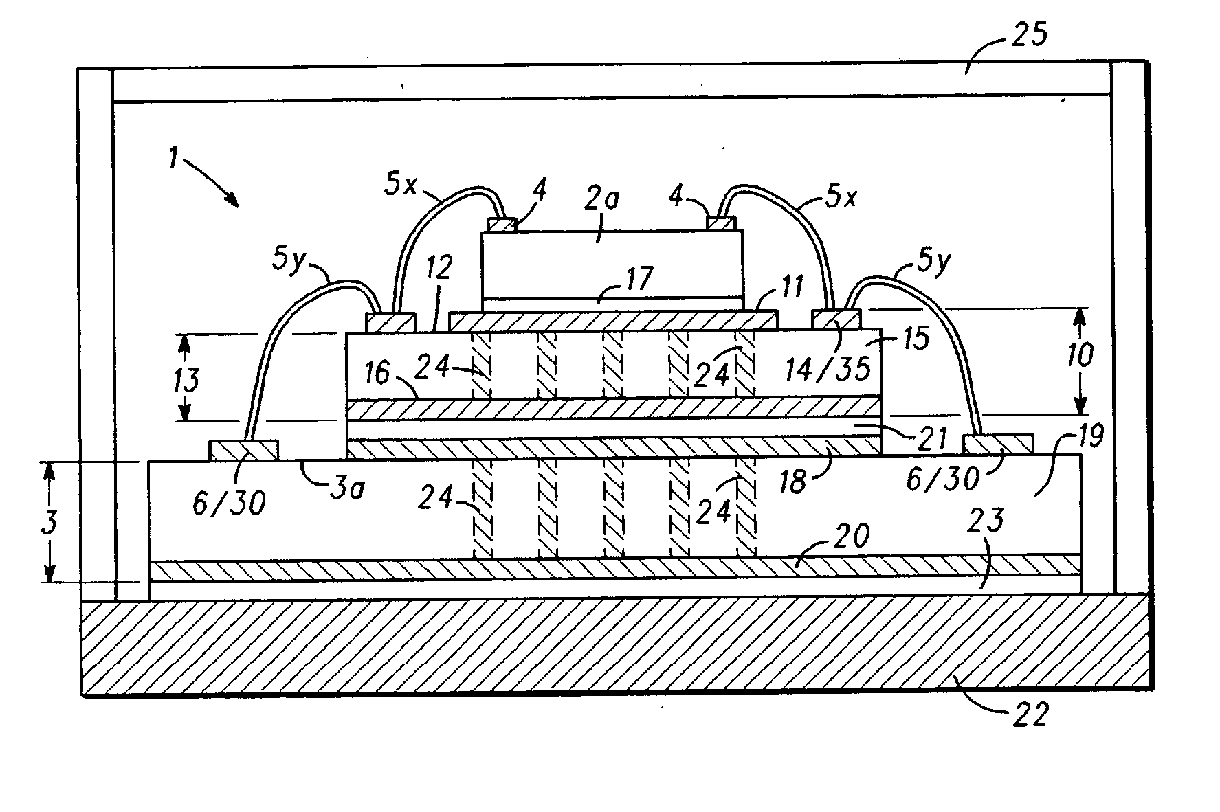
[0016] In an embodiment of the present invention, a mounting structure for mounting an IC on a substrate, which is particularly useful in the context of a MCM, is disclosed. The mounting structure intervenes between the IC and the MCM substrate, and promotes heat dissipation from the IC. The mounting structure, however, is isolative, and in one embodiment comprises a direct bond to copper (DBC) board. On one of the conductive sides of the DBC board, a heat spreading region is formed in the center with bond pad areas around the heat spreading region at the periphery of the DBC. The IC is mounted to the heat spreading region to assist is heat dissipation from the IC. The other side of the mounting structure is mounted to the substrate, which also has bond pads. In an embodiment of the present invention, bond pads on the IC are connected to the bond pad areas on the mounting structure, and the bond pad areas on the mounting structure are further coupled to the bond pads on the substrat...


PUM


Abstract

Disclosed is a mounting structure for mounting an IC on a substrate, and particularly useful in a Multi-Chip Module (MCM). The mounting structure intervenes between the IC and the MCM substrate, and promotes heat dissipation from the IC. The mounting structure is insulative, and preferably comprises a direct bond to copper (DBC) board. A heat spreading region to which the IC is affixed is formed on a surface of the mounting structure with bond pad areas are around the heat spreading region. The other side of the mounting structure is mounted to the substrate, which also has bond pads. Bond pads on the IC are connected to the bond pad areas on the mounting structure, and the bond pad areas on the mounting structure are further coupled to the bond pads on the substrate. Each of these connections is preferably made by wirebonding. Thermal vias can be used in the mounting structure and/or in the substrate to further promote heat dissipation.

Description

BACKGROUND OF THE INVENTION [0001] 1. Field of the Invention [0002] The present invention relates to techniques for mounting an integrated circuit chip to a substrate in a multi-chip module (MCM), and more specifically to a structure having a heat spreader with intermediate bonding pads for connecting the chip to the MCM. [0003] 2. Description of the Related Art [0004] Technical evolution in the field of electronics has resulted in a demand for faster and more compact systems. More advanced applications also necessitate greater numbers of components, which need to communicate with each other. For new systems to meet the requirement of quick access between different components, the length of the paths between different components of the system must be kept within certain limits. However, when the complexity of a system grows, the length of the paths between components also grows. In order not to exceed the maximum allowed distance between such components, these components have been b...

Claims


Application Information

Patent Timeline
IPC IPC(8): H01L23/34
CPCH01L23/3677H01L23/3735H01L23/5382H01L23/5385H01L23/5386H01L24/49H01L2224/48227H01L2224/4911H01L2224/49171H01L2224/73265H01L2924/01004H01L2924/01013H01L2924/01014H01L2924/01029H01L2924/01033H01L2924/01047H01L2924/01057H01L2924/01079H01L2924/01082H01L2924/09701H01L2924/19107H01L24/48H01L2224/32225H01L2924/01006H01L2924/01021H01L2924/014H01L2924/351H01L2924/00014H01L24/73H01L2924/14H01L2224/05554H01L2924/00H01L2924/00012H01L2224/45099H01L2224/05599
Inventor ALHAYEK, IYADBIANCO, GERRYBROSZEIT, JUERGENGAYOWSKY, GREGORYSCHMADLAK, ILKOSOTIROPOULOS, GEORGE
Owner CONTINENTAL AUTOMOTIVE SYST INC
Why Eureka
Try Eureka