DC brush-free motor and fan rotated by outer rotor having annular ferrite magnet with alignment on its inner periphery

a technology of annular ferrite magnet and dc brush-free motor, which is applied in the direction of positive displacement liquid engine, pump, machine/engine, etc., can solve the problems of high cost, difficult production, and high price of articles made of it, so as to increase the effect of magnetic energy accumulation, shorten the magnetic loop, and increase the efficiency of dc brush-free motor

Inactive Publication Date: 2007-04-26
SUPER ELECTRONICS
View PDF8 Cites 14 Cited by
  • Summary
  • Abstract
  • Description
  • Claims
  • Application Information

AI Technical Summary

Benefits of technology

[0021] 2. When it is used on a fan, the outer rotor is directly provided on its outer portion with fan blades; in rotating the outer rotor, the blades of the fan synchronically rotates with the outer rotor, an effect of air blowing can thus be achieved by rotating of the fan blades.
[0022] In addition to these, the object of dividing the annular ferrite magnet with grain alignment on its inner periphery into the magnetic inner layer and the magnetic conductive outer layer is to make magnetic fluxes of the magnetic inner layer turn back right away when they pass the magnetic conductive outer layer to thereby shorten the magnetic loops, and to in

Problems solved by technology

The magnetic characteristics of such material surely can satisfy requirements, but it has a defect in having high cost (neodymium is rare metal with smaller yield of production) and is difficult to be produced, hence an article made of it is quite expensive.
By the problem resided in technical processing of such outer rotor magnets, such mag

Method used


Image

  • DC brush-free motor and fan rotated by outer rotor having annular ferrite magnet with alignment on its inner periphery
  • DC brush-free motor and fan rotated by outer rotor having annular ferrite magnet with alignment on its inner periphery
  • DC brush-free motor and fan rotated by outer rotor having annular ferrite magnet with alignment on its inner periphery

Examples


Embodiment Construction

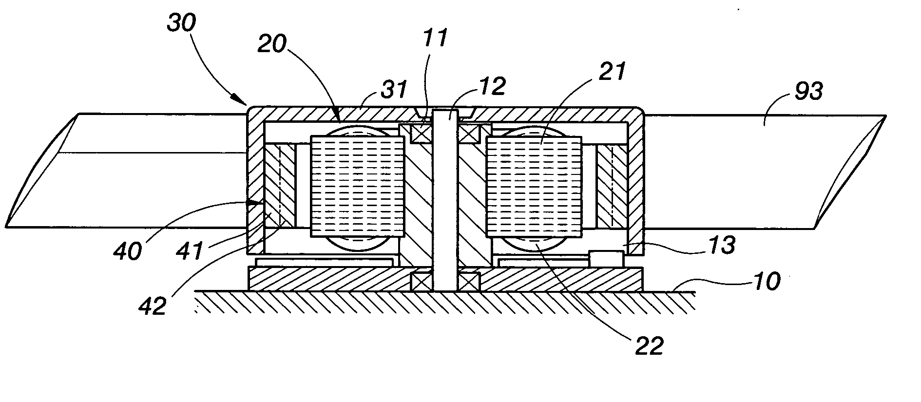
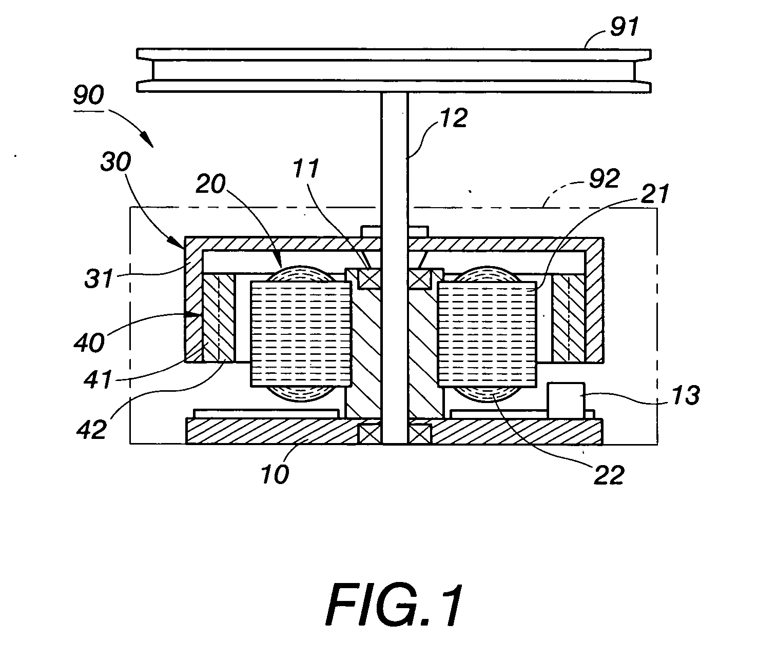
[0027] In a first embodiment of the present invention as shown in FIG. 1 which is a perspective view showing the structure of a DC brush-free motor 90 rotated by an outer rotor, the DC brush-free motor 90 puts out power through rotating of a rotating axle. In the drawing, the rotating axle is provided on its front end with a belt pulley 91, when the rotating axle is rotated, the belt pulley 91 is rotated to put out power. Certainly, the front end of the rotating axle can be provided with fan blades or other necessary rotation driving elements.

[0028] In this embodiment, the DC brush-free motor 90 rotated by an outer rotor is provided internally with a base 10, a stator 20 and the outer rotor 30 surrounding the stator 20. Wherein:

[0029] the base 10 is fixed in a housing 92 of the DC brush-free motor 90 for assembling and positioning of the stator 20 and the outer rotor 30, and is provided centrally with a rotating axle 12 to be rotated by providing of a bearing 11, it is provided on...


PUM


Abstract

A DC brush-free motor or fan rotated by an outer rotor having an annular ferrite magnet with grain alignment on its inner periphery, the main body of the motor or fan is composed of a base, a stator and an outer rotor surrounding the stator; the outer rotor includes a rotating disk and the annular ferrite magnet fixed on an inner periphery of the rotating disk, the annular ferrite magnet is a multipolar anisotropic permanent magnet, the main body of the annular magnet is divided into a magnetic conductive outer layer which is not magnetic and a magnetic inner layer, fluxes of the inner layer turn back when they pass the outer layer to thereby shorten the magnetic loops, and to increase magnetic force and the effect of magnetic energy accumulation. When the motor runs, the outer rotor drives a rotating axle (on the base) extended out of a housing to put out power and to be a power output axle of the motor. As to the fan, the outer rotor is provided on its outer portion with fan blades, an effect of air blowing can be achieved by rotating the fan blades.

Description

BACKGROUND OF THE INVENTION [0001] 1. Field of the Invention [0002] The present invention relates to a DC brush-free motor or a fan rotated by an outer rotor, and especially to a DC brush-free motor or a fan having an annular ferrite magnet with grain alignment on its inner periphery in order to increase magnetic force and the effect of magnetic energy accumulation, and further to increase the efficiency of the DC brush-free motor and the fan. [0003] 2. Description of the Prior Art [0004] According to the evaluation of the Electric Power Researching Institution of the U.S.A., consumption of electric energy in the recent years has been 40% of the amount of total energy source consumption, and the ratio of supplying electric energy for electric appliances is largely raised following the rising of the quality of living. [0005] It is estimated that by the year of 2010, there will be 80% of energy source to supply for electric appliances, wherein energy source consumption of motors will ...

Claims


Application Information

Patent Timeline
IPC IPC(8): H02K7/00H02K21/12H01L41/00
CPCH02K1/2786H02K7/14H02K29/08H02K1/2791H02K7/18
Inventor CHEN, CHI-WEN
Owner SUPER ELECTRONICS
Why Eureka
Try Eureka