Server pool management method

Inactive Publication Date: 2007-04-26
HITACHI LTD
View PDF13 Cites 177 Cited by
  • Summary
  • Abstract
  • Description
  • Claims
  • Application Information

AI Technical Summary

Benefits of technology

[0011] The object of this invention is to provide a system in which the time required to retrieve a standby host from a virtual repository (server pool) and build it in a business system is shortened, and an unexpec

Problems solved by technology

The information system, therefore, normally holds excessive computer resources for a light load, and poses the problem of how effectively the computer resources are to be utilized.
In the prior art, the entire disk image (software) of the computers in operation are copied to the standby computers to be made available, and therefore the preparation time consumes too much time.
Specifically, in copying the disk image of the computer in operation (active host) of a business system, the time requ

Method used


Image

  • Server pool management method
  • Server pool management method
  • Server pool management method

Examples


first embodiment

[First Embodiment]

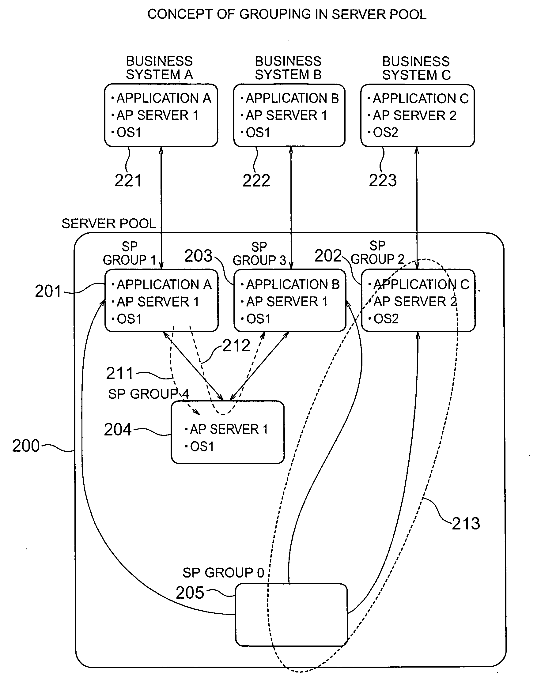
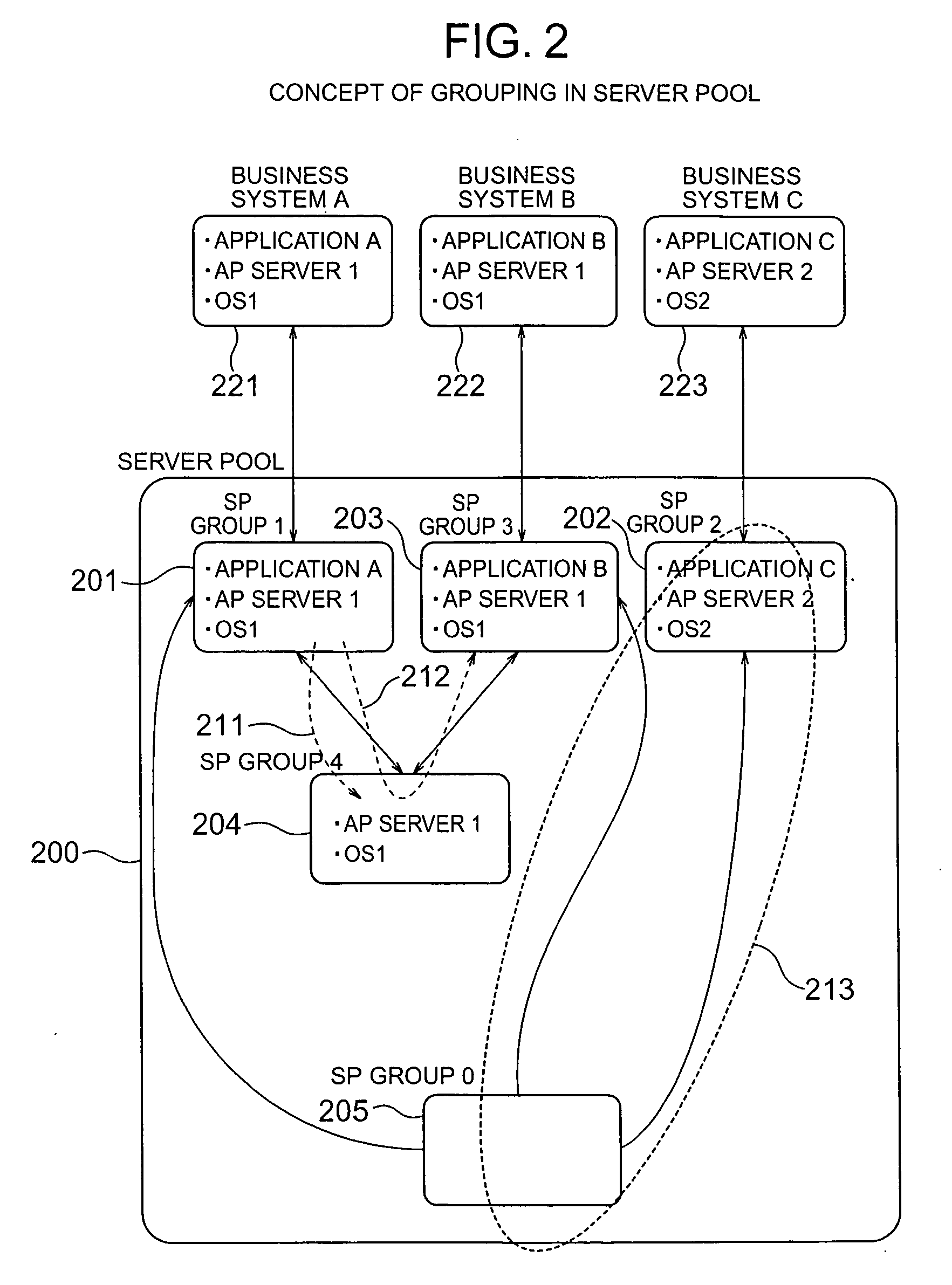
[0084] The standby hosts associated with the server pool are divided into groups in accordance with the software constituting the active host operated to process a business system. An embodiment is described below in which the business system with which a standby host is associated is changed in accordance with the frequency of use thereby to optimize the number of the standby hosts included in a group.

[0085] An example of a physical configuration of an information system for processing various business systems is shown in FIG. 4. According to this embodiment, a total of 15 hosts including active hosts, standby hosts and a management host are used.

[0086] A load balancer 430 is a load distributor which has such a function that the requests sent from the user to the information system through the Web application are distributed to the active hosts in the information system and the result of response from the active hosts is returned to the user. A network switch 44...

second embodiment

[Second Embodiment]

[0146] Each host is so configured as not to include, or if included, not to use the HDD. The logic unit (LU) included in the storage is used as the HDD of the host, and the host is started using the LU. In this configuration, a method of searching for the LU most quickly assignable to the business system is explained below. According to this embodiment, the server pool 130 includes the LU, i.e. the SP groups 0 to 4 shown in FIG. 2 include the LU.

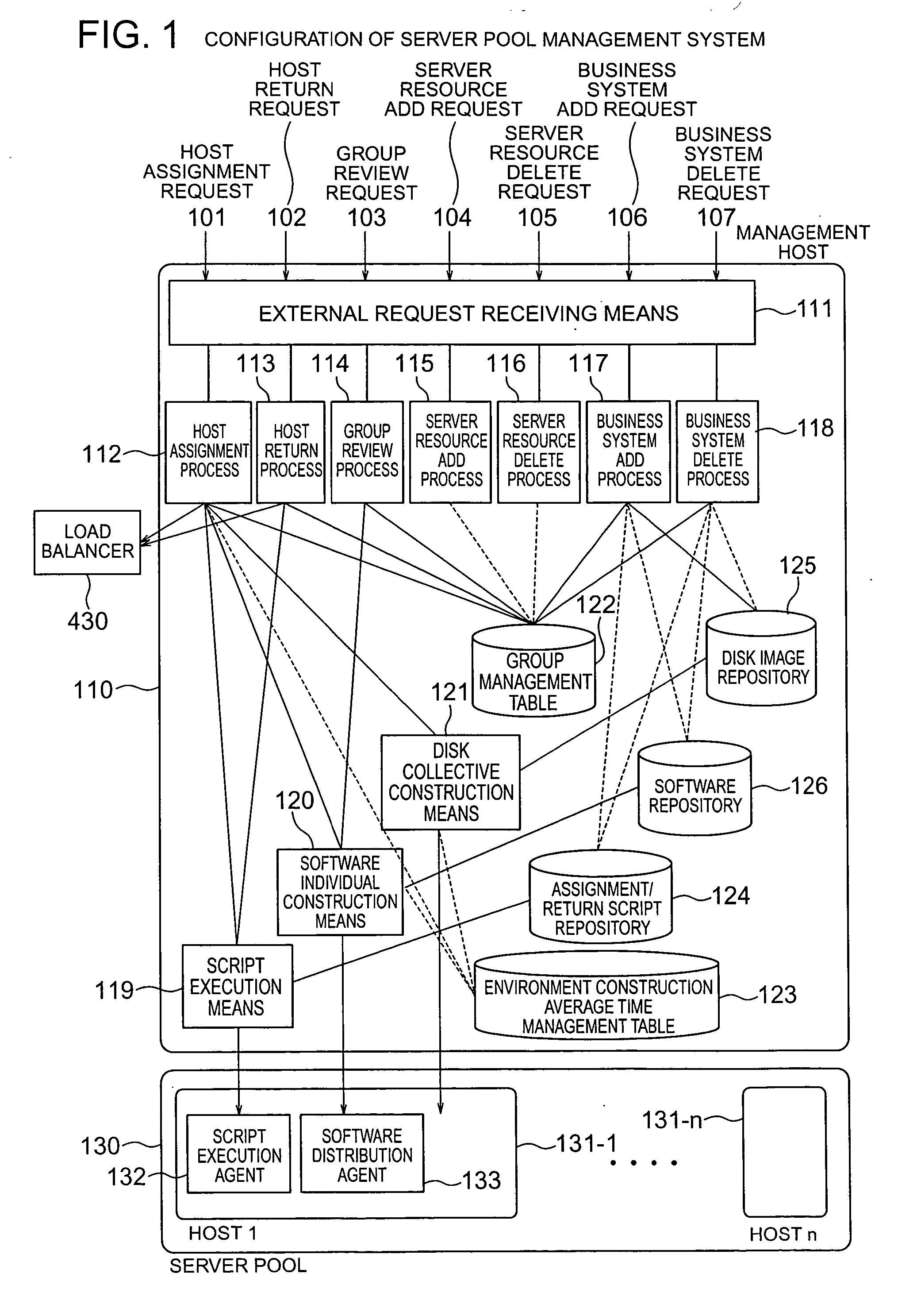
[0147]FIG. 17 is a diagram showing a system configuration. As compared with the first embodiment, this system additionally includes a host management table 1701, a LU operation means 1702, a LU add process 1707, a LU delete process 1708, a storage unit 1703 and a fibre channel switch 1704. The host management table 1701 manages as to which host 300 is busy and which host 300 is unbusy. The LU operation means 1702, operating the fibre channel switch 1704, assigns the LU to and makes available a specified host 300 or cancel...

third embodiment

[Third Embodiment]

[0180] The first and second embodiments are intended for a system which can realize the scale-out and scale-in states through the load balancer. According to this embodiment, on the other hand, a method is explained in which a plurality of users share the hosts 300 fewer than the users, and a host 300 capable of constructing the environment for the users most quickly is selected in preparation for application.

[0181]FIG. 30 is a diagram showing the logic configuration of a business according to this embodiment. The host 300 prepared in this embodiment holds the software environment, and the data prepared for each user 3001 is stored in another storage unit (area). Also, in order to use the host 300, each user is assumed to use a client host 3002. The client host 3002, connected to the network, can receive and display the screen of the host 300 of which the environment is constructed using the server pool management system 3000.

[0182] A host use preparation means 3...


PUM


Abstract

Standby computers are dynamically divided into groups according to the difference between the software thereof and the software required of a business system. When a computer is made available, the standby computers divided into groups by software structure are searched and an appropriate one is extracted to quickly complete the construction of the software environment. An active computer, if to be transferred to standby mode, is associated with the group having the same software structure as the business system with which the active computer has thus far operated. The active/standby states of the computers are monitored, and the standby computers are changed thereby to widen the possible range of application to other business systems, removing copy operation of disk images from the active computer to the standby computers.

Description

BACKGROUND OF THE INVENTION [0001] This invention relates to an information system for providing a part of a plurality of computer resources and the function thereof to a plurality of business systems of customers, or in particular to a management technique of an information system adapted to meet sharp changes of the processing request of each business system. [0002] An information system finds practical applications in which a part of a plurality of computer resources and the function thereof are provided to on-demand service providers and data centers mainly dealing with the batch processing or customers who are required to handle / process a predetermined amount of accesses and data processing jobs within a predetermined period of time. [0003] The importance of constructing a business system using this information system and reducing the cost by improving the business efficiency has been widely recognized, and demand for this information system has been ever on the increase. In th...

Claims


Application Information

Patent Timeline
IPC IPC(8): G06F15/173
CPCH04L67/1008H04L67/1002H04L67/1012G06F8/61G06F8/62G06F9/5011G06F9/5055H04L67/1001
Inventor TAKANO, HIDEKITAKASHIGE, SOICHI
Owner HITACHI LTD
Why Eureka
Try Eureka