Thermal processing method and thermal processing unit

Inactive Publication Date: 2007-05-03
TOKYO ELECTRON LTD
View PDF18 Cites 6 Cited by
  • Summary
  • Abstract
  • Description
  • Claims
  • Application Information

AI Technical Summary

Benefits of technology

[0015] In the case, nevertheless the thermal processing unit has relatively simple structure; a large amount of cooling gas can be introduced dispersedly i

Problems solved by technology

This type of conventional thermal processing unit is designed in such a manner that a thermal process is conducted in a relatively high temperature zone of, for example, about 900° C. to 1200° C. In addition, in this type of conventional thermal processing unit, after the thermal process, it is difficult for the temperature of the wafer to be lowered.
However, in the convent

Method used


Image

  • Thermal processing method and thermal processing unit
  • Thermal processing method and thermal processing unit
  • Thermal processing method and thermal processing unit

Examples


Embodiment Construction

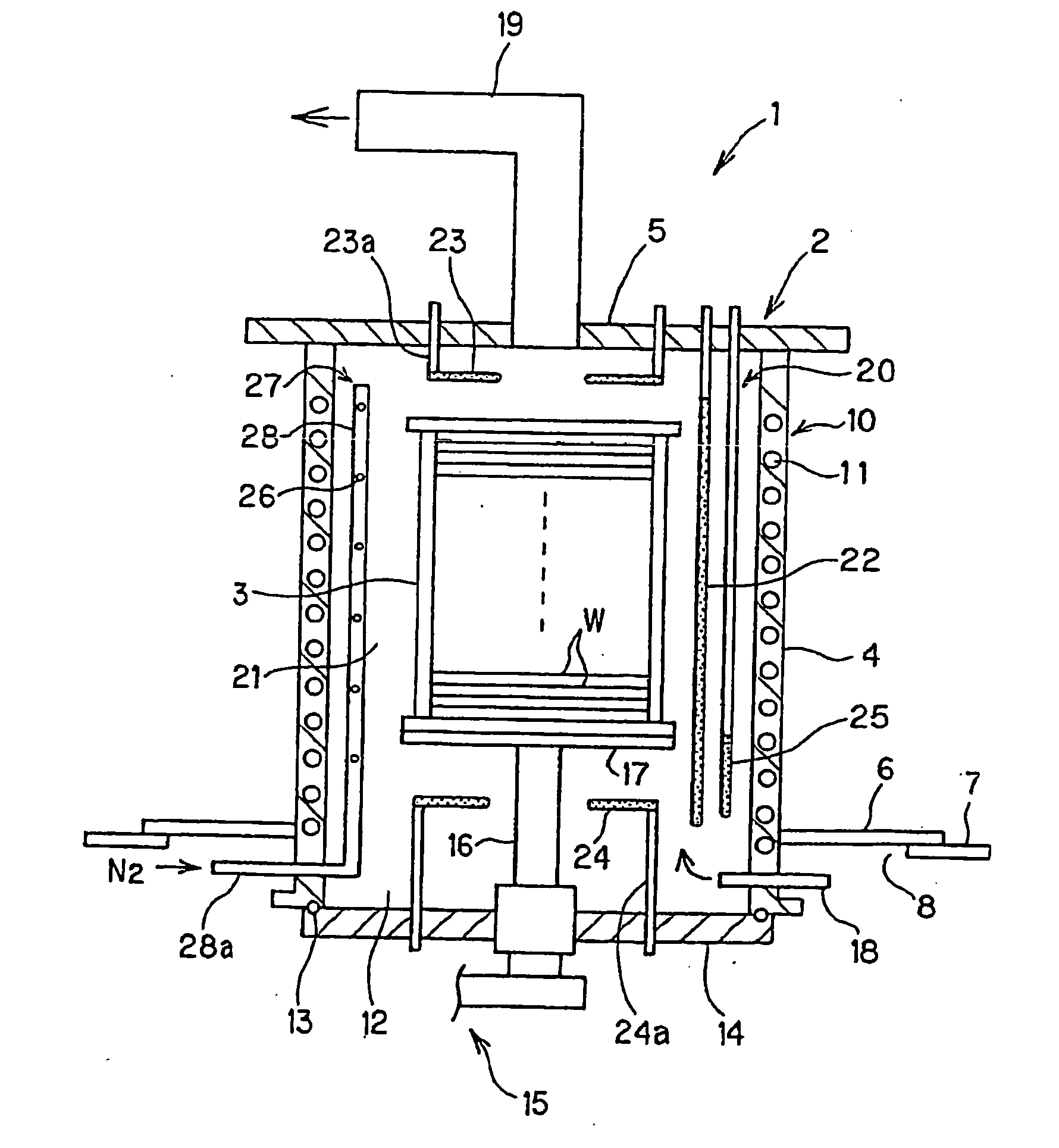
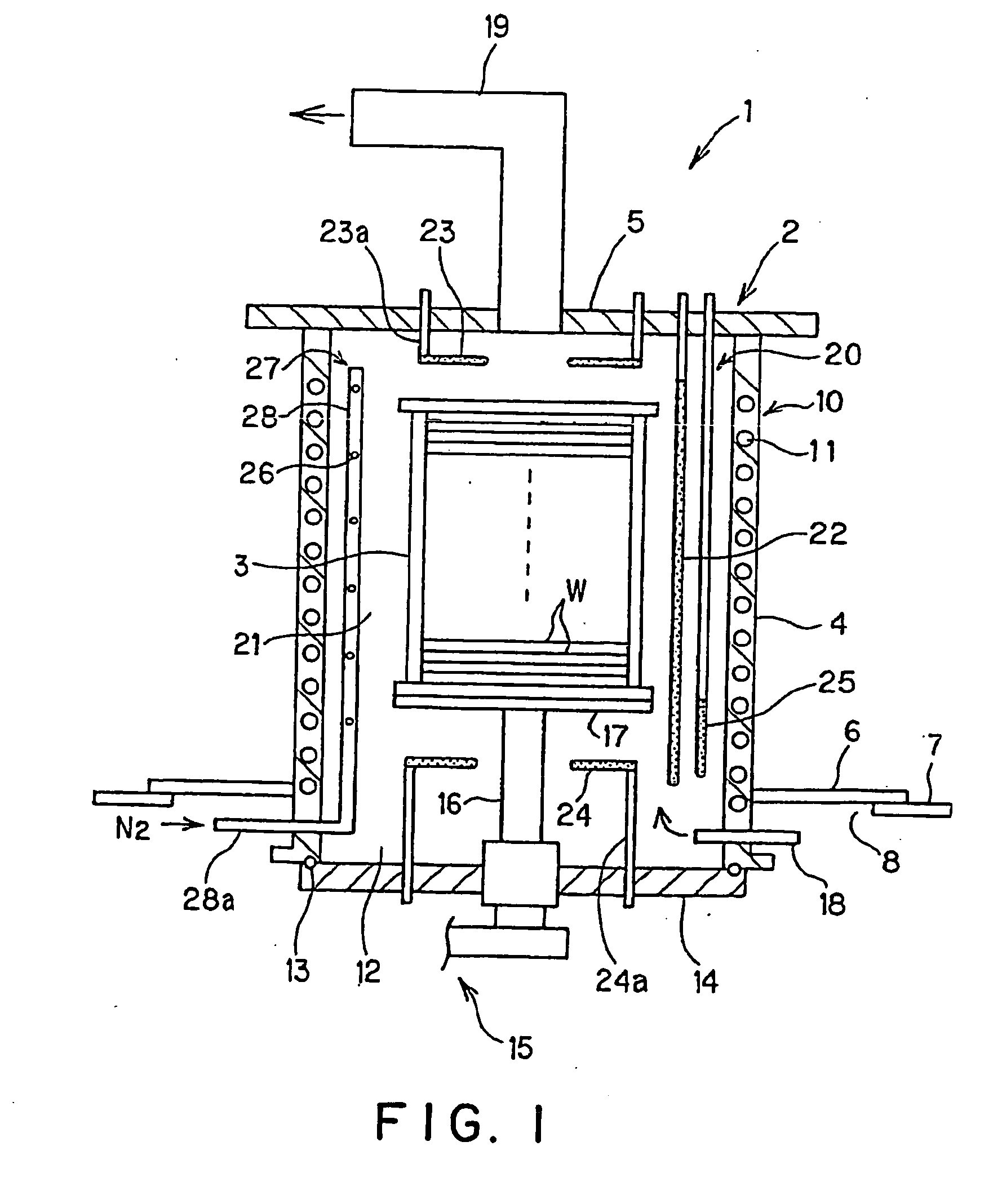
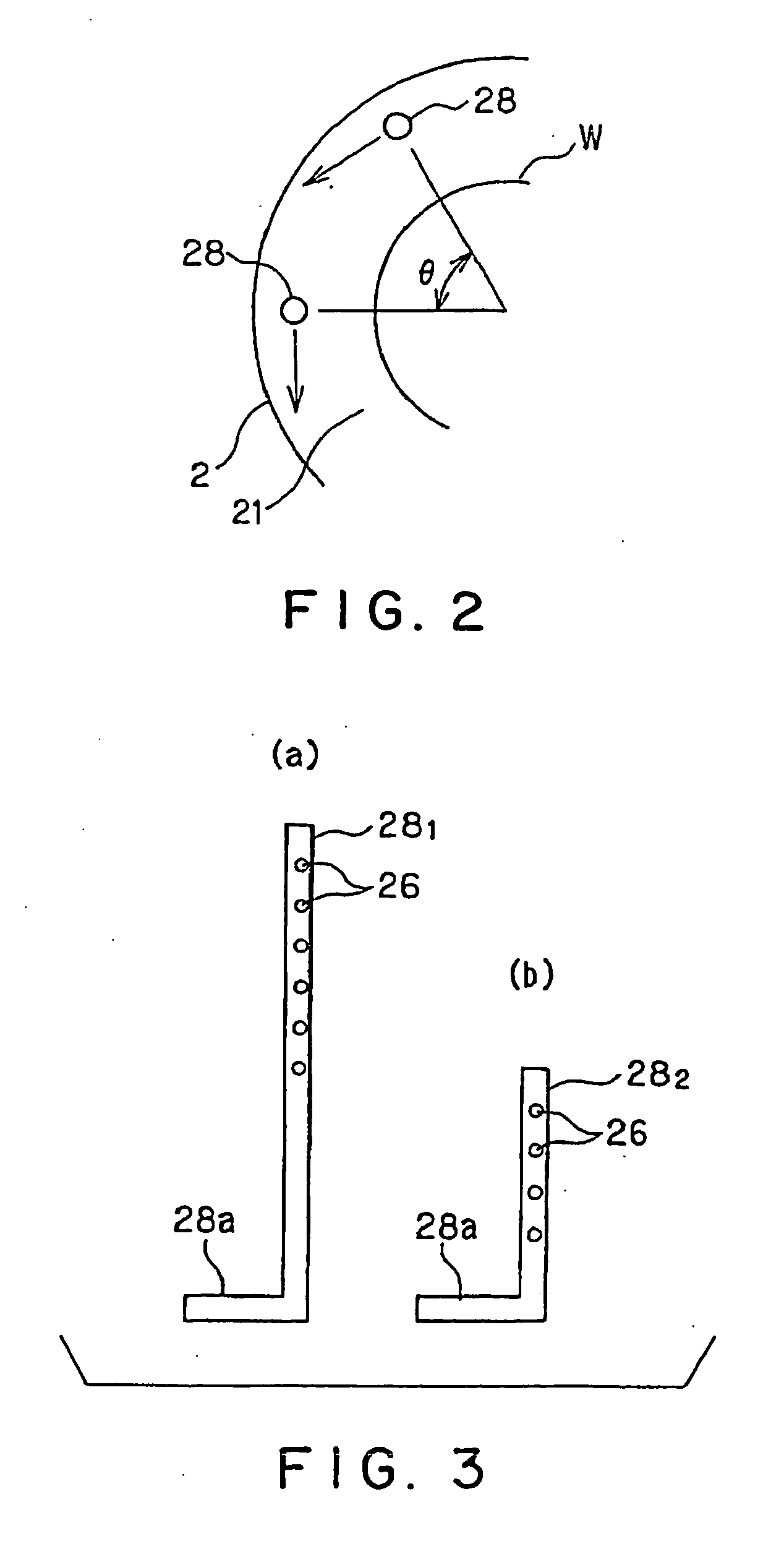
[0028] Hereinafter, embodiments of the present invention are explained in detail with reference to the attached drawings. FIG. 1 is a longitudinal sectional view showing a thermal processing unit of an embodiment according to the present invention. FIG. 2 is a schematic transversal sectional view showing an example of arrangement of cooling-gas blowing-out pipes in a processing container. FIG. 3 is a view for explaining an example of combination of cooling-gas blowing-out pipes. FIGS. 4A to 4C are views showing another embodiment of cooling-gas blowing-out pipes. FIG. 4A is a schematic transversal sectional view showing an example of arrangement of the cooling-gas blowing-out pipes in a processing container. FIG. 4B is a side view of the cooling-gas blowing-out pipe. FIG. 4C being a partial enlarged sectional view showing a main part of FIG. 4B. FIG. 5 is a schematic plan view showing an example of lower heater in a processing container. FIG. 6 is a graph showing a comparison result...


PUM

PropertyMeasurementUnit
Temperatureaaaaaaaaaa
Flow rateaaaaaaaaaa

Abstract

The present invention is a thermal processing method including: a step of conducting a predetermined thermal process in a low temperature zone to a plurality of objects to be processed held in a tier-like manner by a heating unit, in a processing container that is made of metal and has the heating unit therein, and a step of introducing a cooling gas into respective areas in the processing container divided in a height direction of the objects to be processed.

Description

FIELD OF THE INVENTION [0001] This invention relates to a thermal processing method and a thermal processing unit for conducting a thermal process to an object to be processed. BACKGROUND ART [0002] In order to manufacture a desired semiconductor unit, various thermal processes including an oxidation process, a diffusion process, a CVD process, an annealing process or the like are carried out to an object to be processed such as a semiconductor wafer. As a thermal processing unit for conducting the processes, a vertical thermal processing unit is used wherein a large number of wafers are thermally processed at a time. [0003] The vertical thermal processing unit has a processing container made of quartz, which forms a vertical thermal processing furnace. A furnace opening that opens at a lower end of the processing container can be opened and closed by a lid. A boat (holding tool) made of quartz that holds a large number of wafers in a tier-like manner is supported on the lid via a h...

Claims


Application Information

Patent Timeline
IPC IPC(8): B05D3/02C23C16/00H01L21/768H01L21/00H01L21/22H01L21/31H01L21/324H01L23/522
CPCH01L21/67109H01L21/324
Inventor SAITO, TAKANORISERIZAWA, KAZUHIDEICHIKAWA, TAKASHI
Owner TOKYO ELECTRON LTD
Why Eureka
Try Eureka