Body bias coordinator, method of coordinating a body bias and sub-circuit power supply employing the same

Active Publication Date: 2007-05-03
TEXAS INSTR INC
View PDF5 Cites 4 Cited by
  • Summary
  • Abstract
  • Description
  • Claims
  • Application Information

AI Technical Summary

Benefits of technology

[0007] To address the above-discussed deficiencies of the prior art, the present invention provides a body bias coordinator for use with a transistor employing a body region. In one embodiment, the body bias coordinator includes a control unit configured to control the transistor and make it operable to provide a virtual supply voltage from a source voltage during activation of the transistor. The body bias coordinator also includes a connection unit coupled to the control unit and configured to connect the body region to the virtual supply voltage during activation of the transistor. In an alternative embodiment, the connection unit is further configured to connect the body region to another voltage during non-activation of the transistor. These embodiments improve transistor active and passive performance, permit smaller transistor sizing and reduce leakage current.

Problems solved by technology

For example, these circuit blocks may have their operating power completely removed when they become operationally inactive for a period of time.
However, there is a capacitance associated with the body nodes of the header and footer transistors, which may be relatively large.
This capacitance requires a dynamic switching power associated with switching a voltage on the body node that may provide too large a penalty to be used in some applications, especially if powering the circuitry on and off is required too frequently.
Additionally, a forward body bias to lower threshold voltage in the active mode gives rise to forward biased diode current that is generally undesirable.

Method used


Image

  • Body bias coordinator, method of coordinating a body bias and sub-circuit power supply employing the same
  • Body bias coordinator, method of coordinating a body bias and sub-circuit power supply employing the same

Examples


Embodiment Construction

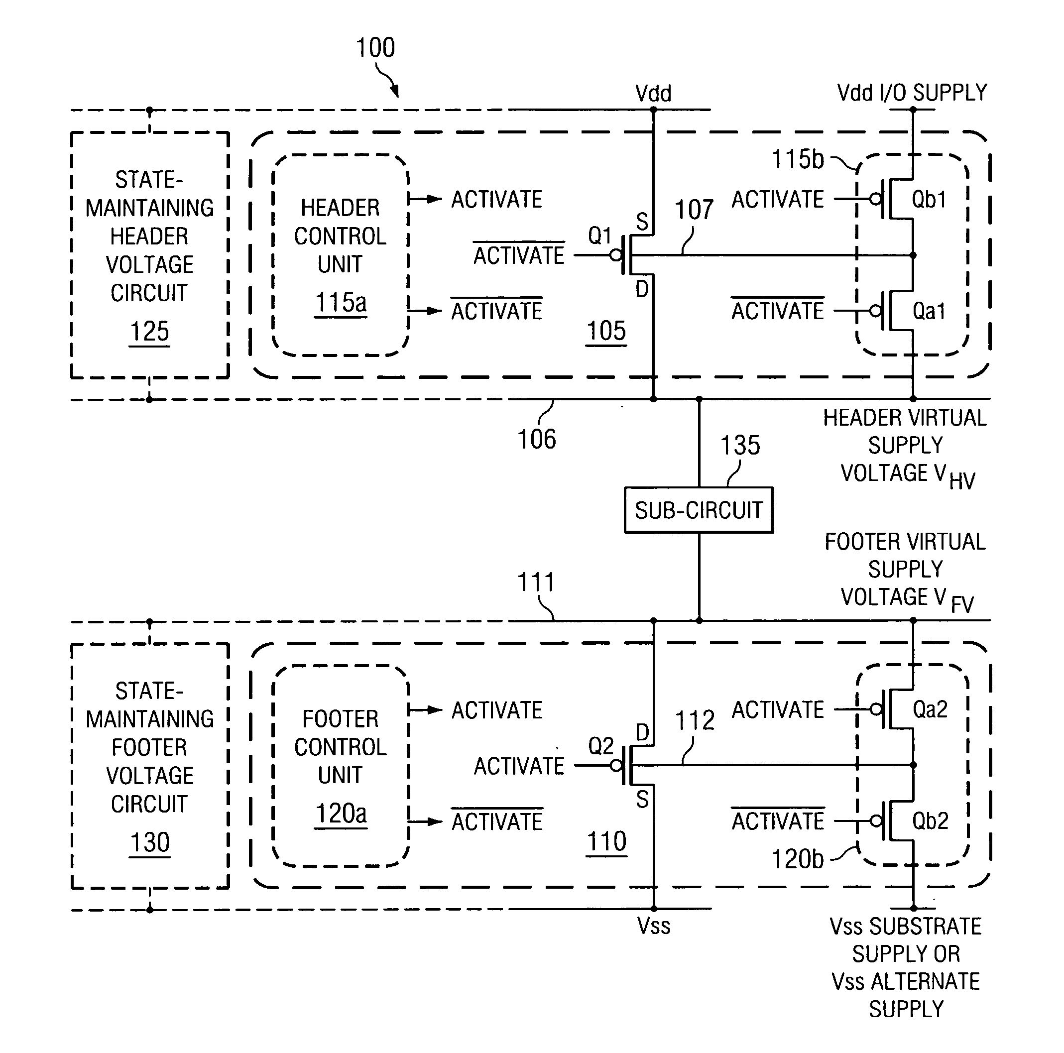
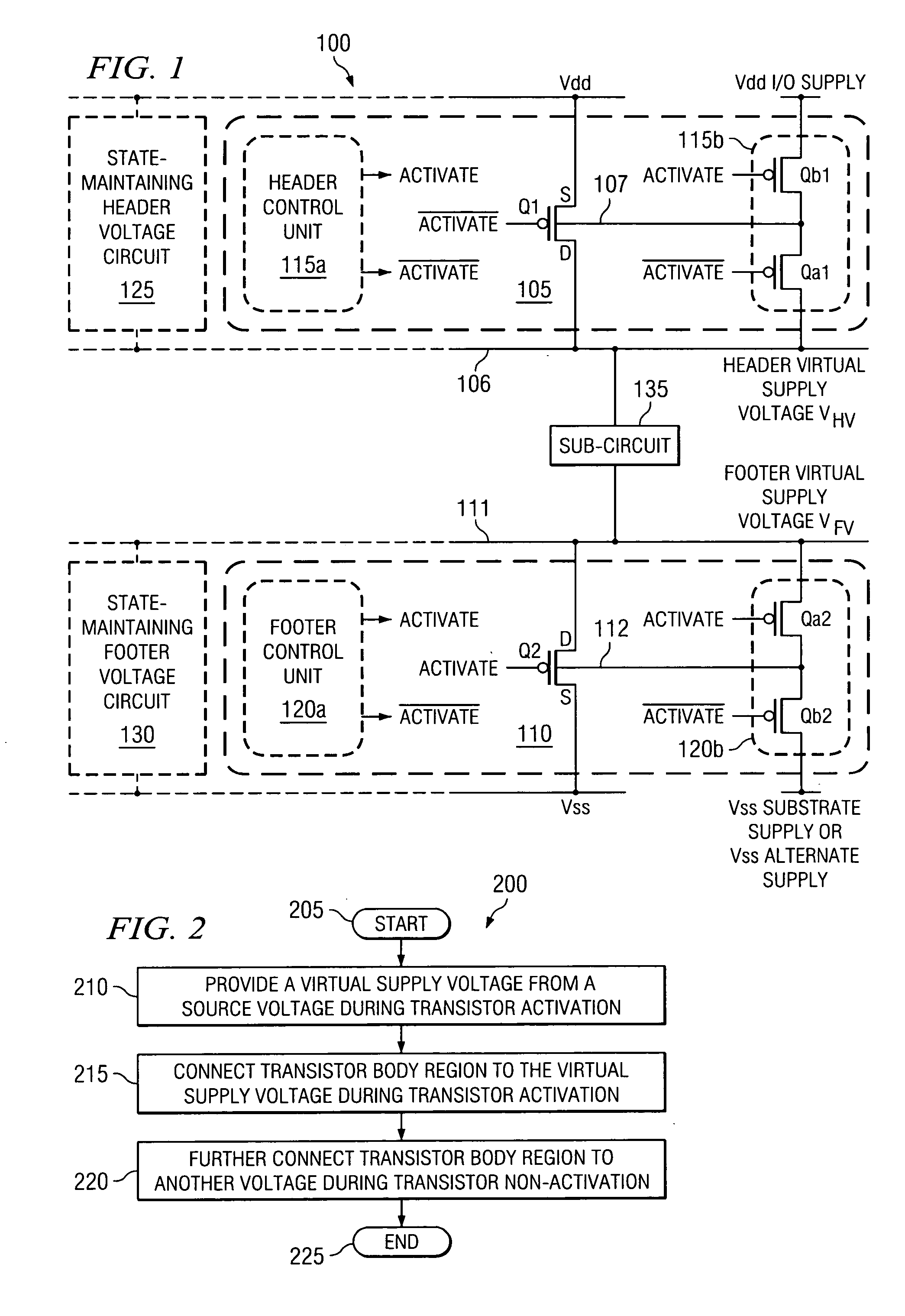
[0014] Referring initially to FIG. 1, illustrated is a circuit diagram of an embodiment of a sub-circuit power supply, generally designated 100, constructed in accordance with the principles of the present invention. The sub-circuit power supply 100 includes a header circuit 105, a footer circuit 110 and a sub-circuit 135. The header circuit 105 includes a header transistor Q1 having a header body region 107 and a header body bias coordinator 115 having a header control unit 115a and a header connection unit 115b. The header connection unit 115b includes first and second header body region switches Qa1, Qb1. The footer circuit 110 includes a footer transistor Q2 having a footer body region 112 and a footer body bias coordinator 120 having a footer control unit 120a and a footer connection unit 120b. The footer connection unit 120b includes first and second footer body region switches Qa2, Qb2. The sub-circuit power supply 100 also includes an optional state-maintaining header voltag...


PUM


Abstract

The present invention provides a body bias coordinator for use with a transistor employing a body region. In one embodiment, the body bias coordinator includes a control unit configured to control the transistor and make it operable to provide a virtual supply voltage from a source voltage during activation of the transistor. The body bias coordinator also includes a connection unit coupled to the control unit and configured to connect the body region to the virtual supply voltage during activation of the transistor. In an alternative embodiment, the connection unit is further configured to connect the body region to another voltage during non-activation of the transistor. These embodiments improve transistor active and passive performance, permit smaller transistor sizing and reduce leakage current.

Description

TECHNICAL FIELD OF THE INVENTION [0001] The present invention is directed, in general, to microelectronics and, more specifically, to a body bias coordinator, method of coordinating a body bias and a sub-circuit power supply employing the coordinator or the method. BACKGROUND OF THE INVENTION [0002] Integrated circuit systems are rapidly increasing in device count and operating speed. Each of these attributes tends to increase power requirements directly while both together cause power requirements to increase exponentially. Therefore, dealing with power requirements associated with integrated circuit systems is becoming a much more critical design arena than before. These power requirements and their corresponding temperature effects have led to the need for additional power management considerations and techniques. [0003] One such management technique involves separating the integrated circuits that require full power all of the time to perform their intended tasks from those that...

Claims


Application Information

Patent Timeline
IPC IPC(8): H03K3/01
CPCH03K17/687H03K19/0016H03K2217/0018H03K2217/0036
Inventor HOUSTON, THEODORE W.MARSHALL, ANDREW
Owner TEXAS INSTR INC
Why Eureka
Try Eureka