
Spread-spectrum radio utilizing MEMS components

a technology of mems components and spread-spectrum radios, applied in the direction of transmission, electrical equipment, impedence networks, etc., can solve the problems of limiting factors such as the size and power required by voltage controlled oscillators, the inability to ensure the transmission of classified information, and the difficulty of radio signals to detect and decode. , to achieve the effect of high q factor, compact size and desirable performance characteristics

Active Publication Date: 2007-05-03
AVAGO TECH INT SALES PTE LTD
View PDF13 Cites 26 Cited by
  • Summary
  • Abstract
  • Description
  • Claims
  • Application Information

AI Technical Summary

Benefits of technology

[0002] A spread-spectrum radio, such as a frequency-hopping spread-spectrum radio or a direct-sequence spread-spectrum radio, includes a transmitter that utilizes microelectromechanical systems (MEMS) based oscillation system to generate a spread-spectrum signal and / or a receiver that utilizes a MEMS-based frequency selection system to receive a spread-spectrum signal. In an embodiment, the MEMS-based oscillation system and the MEMS-based frequency selection system utilize MEMS resonators such as thin film bulk acoustic resonators (FBARs) that are fabricated in high density on a single substrate. The FBAR resonators exhibit desirable performance characteristics including compact size, a high Q factor, and low power consumption. Because the transmitters and receivers utilize MEMS components to generate and filter a spread-spectrum signal, a spread-spectrum radio can be made much smaller and more energy efficient than conventional spread-spectrum radios.

Problems solved by technology

Because normal radio communications can be intercepted by anyone with a receiver, they lack the security required for transmission of classified information.
During World War II, frequency hopping was used to make radio signals more difficult to detect and decode.
The size and power required by these voltage controlled oscillators can be limiting factors in producing compact power efficient radio devices.

Method used


Image

  • Spread-spectrum radio utilizing MEMS components
  • Spread-spectrum radio utilizing MEMS components
  • Spread-spectrum radio utilizing MEMS components

Examples


Embodiment Construction

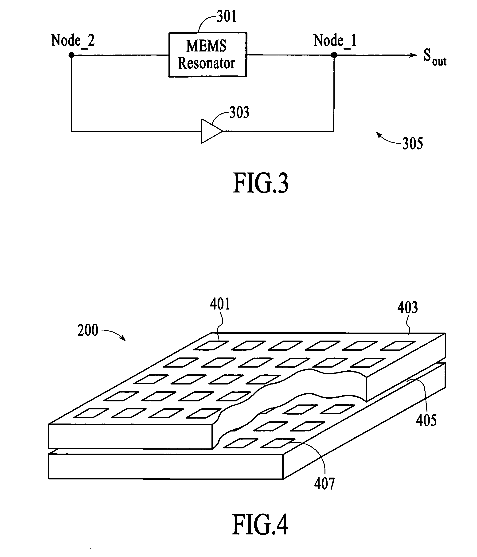
[0014] A spread-spectrum radio, such as a frequency-hopping spread-spectrum radio or a direct-sequence spread-spectrum radio, includes a transmitter that utilizes microelectromechanical systems (MEMS) based oscillation system to generate a spread-spectrum signal and / or a receiver that utilizes a MEMS-based frequency selection system to receive a spread-spectrum signal. In an embodiment, the MEMS-based oscillation system and the MEMS-based frequency selection system utilize MEMS resonators such as thin film bulk acoustic resonators (FBARs) that are fabricated in high density on a single substrate.

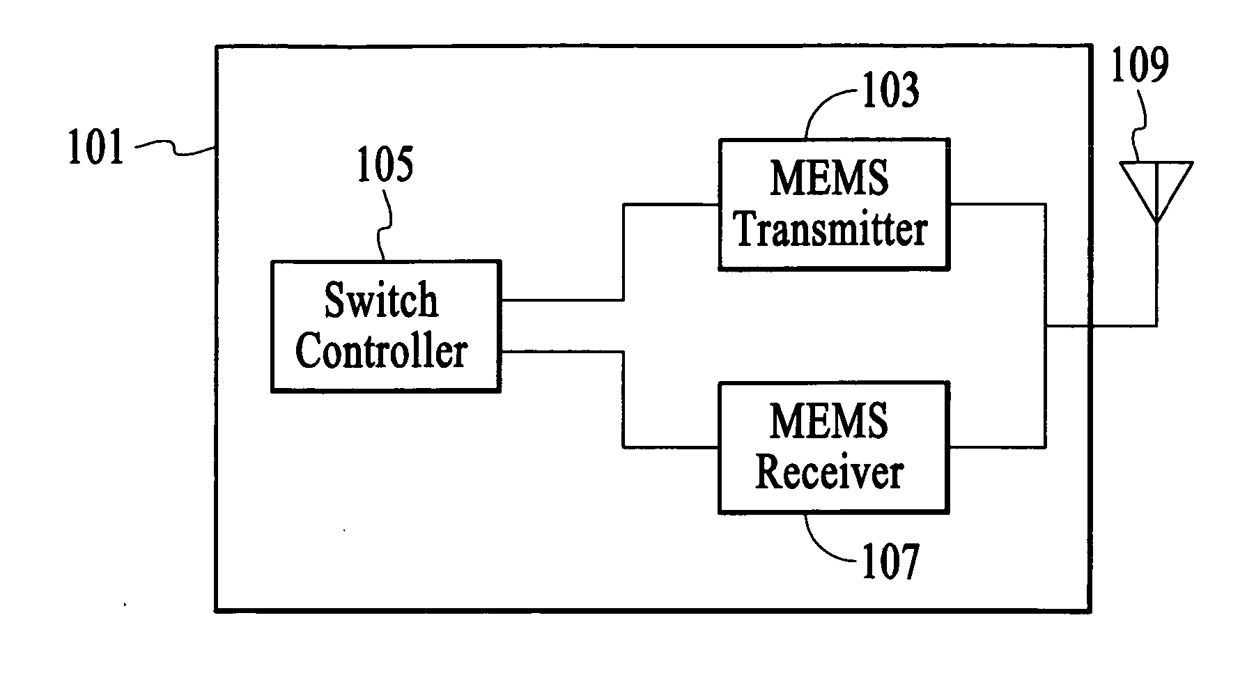
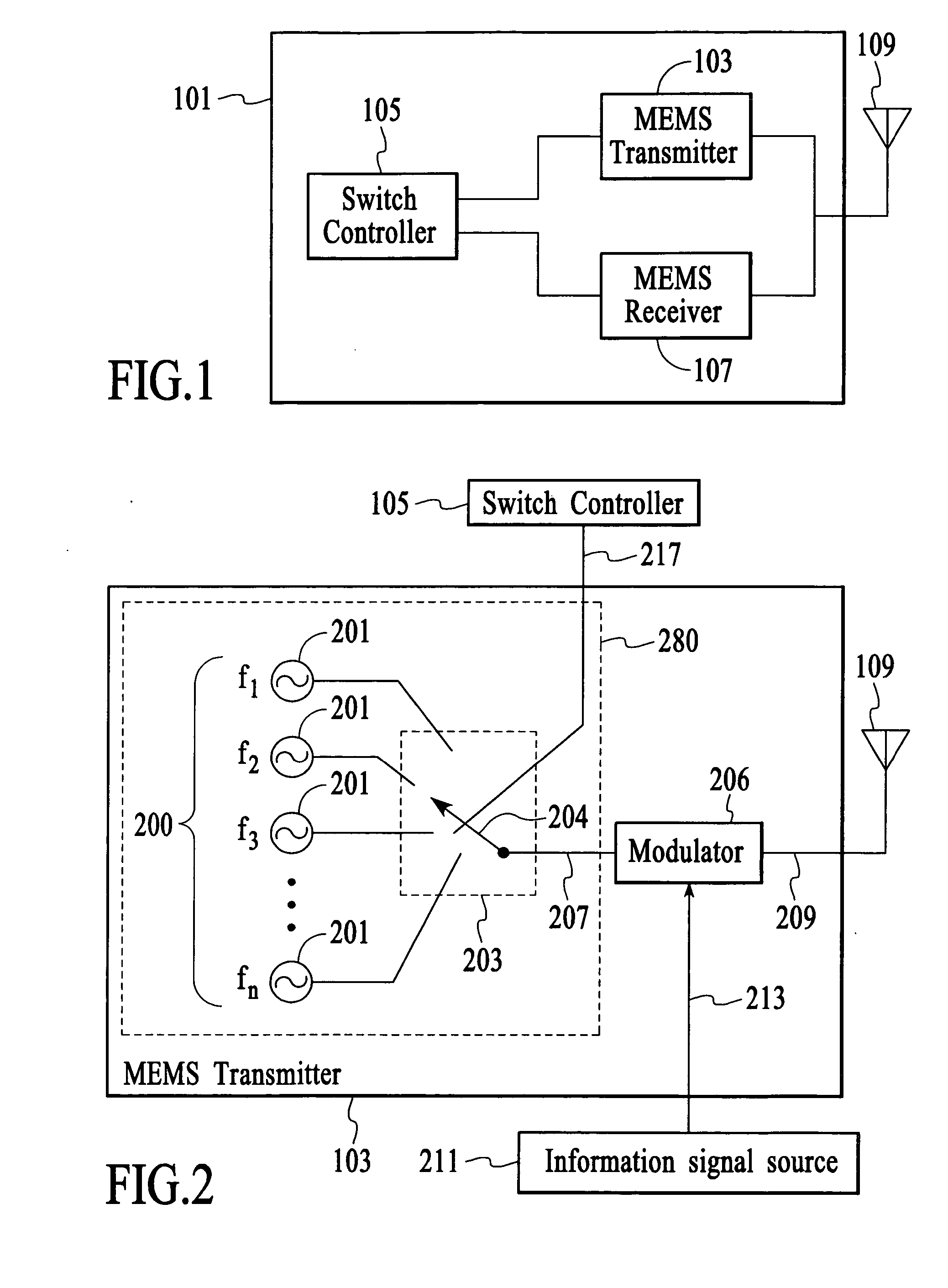
[0015]FIG. 1 depicts a spread-spectrum radio 101 for transmitting and receiving a spread-spectrum signal that has information disposed thereon. In the embodiment of FIG. 1, the spread-spectrum radio utilizes frequency-hopping as is referred to as a frequency-hopping spread-spectrum (FHSS) radio. In an alternative embodiment, the spread-spectrum radio utilizes a direct-sequence spread-spectr...


PUM


Abstract

A spread-spectrum radio, such as a frequency-hopping spread-spectrum radio or a direct-sequence spread-spectrum radio, includes a transmitter that utilizes microelectromechanical systems (MEMS) based oscillation system to generate a spread-spectrum signal and / or a receiver that utilizes a MEMS-based frequency selection system to receive a spread-spectrum signal. In an embodiment, the MEMS-based oscillation system and the MEMS-based frequency selection system utilize MEMS resonators such as thin film bulk acoustic resonators (FBARs) that are fabricated in high density on a single substrate.

Description

BACKGROUND OF THE INVENTION [0001] Because normal radio communications can be intercepted by anyone with a receiver, they lack the security required for transmission of classified information. During World War II, frequency hopping was used to make radio signals more difficult to detect and decode. In frequency hopping, the carrier frequency of a transmitter is rapidly switched among a large set of predetermined frequencies according to a sequence code that is known to the transmitter and must be known by a receiver to decode the communication. Although any radio can receive the frequency-hopped signal, only those radios that know the sequence code are able to decode the transmission. Conventional frequency-hopping radios use multiple fixed frequency voltage controlled oscillators and a switch or a fast-tuning voltage controlled oscillator to generate the different frequencies of the carrier signal. The size and power required by these voltage controlled oscillators can be limiting ...

Claims


Application Information

Patent Timeline
IPC IPC(8): H03H9/70
CPCH03H9/462H03H2007/006H04B1/69
Inventor TRUTNA, WILLIAM R. JR.UNKRICH, MARK A.FLOWER, GRAHAM M.
Owner AVAGO TECH INT SALES PTE LTD
Learn More