[0013] The invention provides an
improved method and apparatus for improving
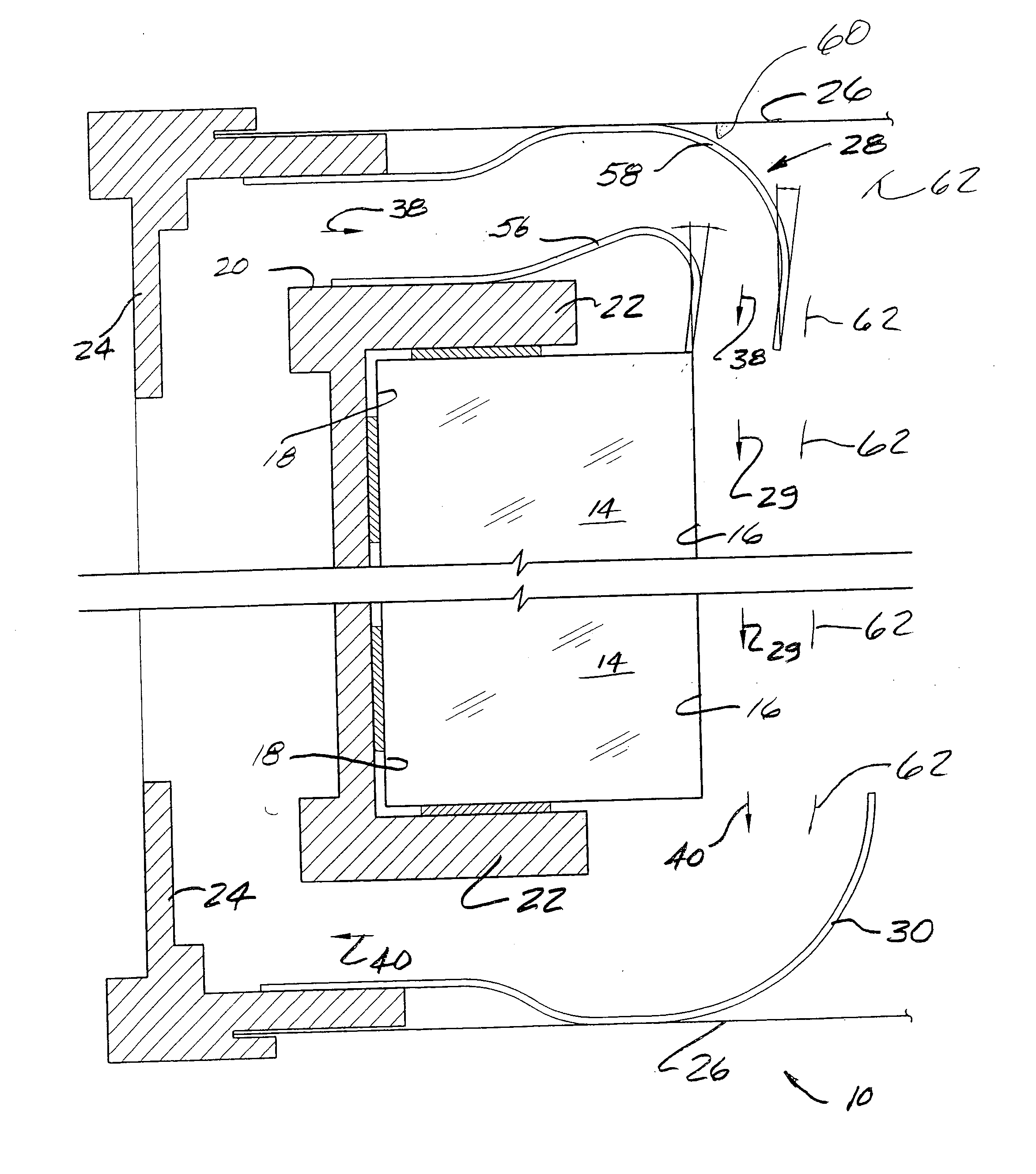
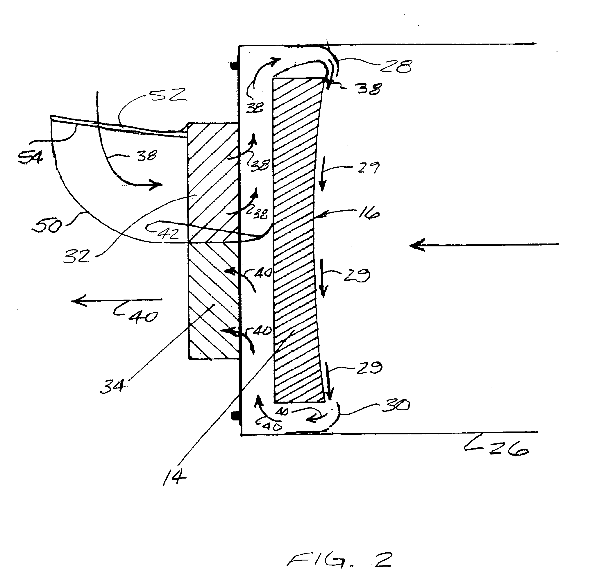
image quality in a reflector-type telescope through utilization of one or more nozzles disposed about the periphery of a reflecting mirror of the telescope, for directing a flow of air from a backside of the mirror across a concave reflecting surface of the mirror. In some forms of the invention, supply nozzles are provided around a portion of the periphery of the mirror, and exhaust pick-up nozzles are provided around another portion of the periphery of the mirror, to thereby cause a flow of air to adhere more closely to the
concave surface of the mirror than is achievable in prior approaches.
[0015] In some forms of the invention, separate, oppositely directed, inflow and outflow fans are provided for generating a flow of supply air to the supply
nozzle, and generating a suction for removing air through the exhaust pick-up nozzles. A divider may be provided between the inflow and outflow fans, to preclude short-circuiting of the air flow directly from the inflow to the outflow fan, without first traveling along the back of the mirror and across the concave reflecting surface. The divider may be provided in a flexible form which will perform the desired function of properly directing the air flow, while still allowing the position of the mirror and
cell to be adjusted with regard to the mounting structure of the telescope.
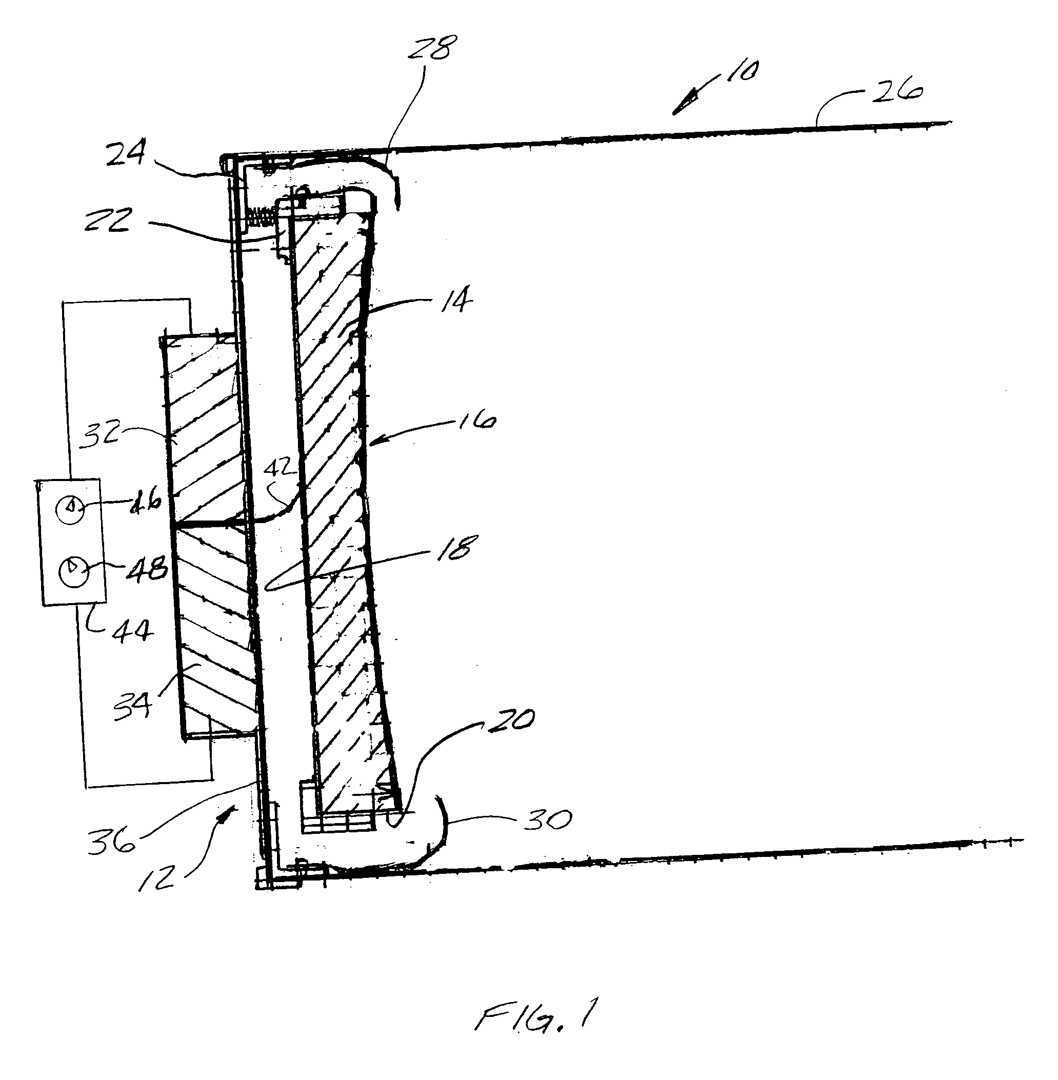
[0016] In some forms of the invention, individual speed controls are provided for the inflow and outflow fans, to allow for
fine tuning of the air flow across the
concave surface of the mirror. In some forms of the invention, for example, one or both of the inflow and / or outflow fans may be operated at maximum speed, when the telescope is first moved to a location where the ambient
air temperature is different from the temperature of the mirror, and then the speed of one or both of the fans may be reduced, as thermal equilibrium is approached, to preclude having the fans induce undesirable vibration into the telescope.
[0019] An apparatus and / or method, according to the invention, effectively and efficiently sweep away the thermal gradient boundary layer, even during cool-down, and / or warm-up, of the mirror, so that the telescope may be used almost immediately when moved out side from an environment having an ambient temperature different from the outdoor ambient temperature. Although the image quality will continue to improve as the mirror temperature is brought into thermal equilibrium with the outdoor ambient
air temperature, within 5 to 15 minutes after the invention establishes air flow across the concave surface of the mirror, image quality is typically so free of
distortion that the further improvement occurring thereafter will be so small as to be undetectable to the eye of most observers.
[0020] Practice of the invention also provides an additional
advantage, in that tube currents are reduced, further enhancing the
clarity of the edge of the image, particularly during the period of time before the mirror temperature has been brought into close proximity to the temperature of the ambient air.
[0021] Furthermore, it has been noted that, due to the highly directed
airflow provided by the invention, and the relatively low
heat transfer capability of the glass mirror, after a very short period of operation of the invention, the reflecting surface of the mirror, which is often formed by a layer of highly thermally conductive aluminum, is rapidly brought to a temperature close to that of the ambient air, even though the remainder of the mirror may still be at a temperature different from the ambient air. In some forms of the invention this effect is enhanced by having the intake
airflow, from intake fan, impinge directly upon the rear surface of the mirror and the
cell, which provides for highly effective and efficient
convective heat transfer to or from the mirror, that tends to achieve the majority of the
heat transfer needed to bring the mirror into equilibrium through the backside of the mirror, rather than through the concave surface.

