
Laser blood flow imaging apparatus

a technology of blood flow and imaging apparatus, which is applied in the field of medical instruments, can solve the problems of loss of reliability of the measurement point itself, increase in the size of the meter itself, and incorrect relationship between values, so as to eliminate waste, ensure the irradiation surface, and efficiently receive only the measurement light

Inactive Publication Date: 2007-05-03
OMEGAWAVE
View PDF5 Cites 26 Cited by
  • Summary
  • Abstract
  • Description
  • Claims
  • Application Information

AI Technical Summary

Benefits of technology

[0014] The present invention has been made to solve the aforementioned technological problems, and a technological object of the invention is to provide a laser blood flow imaging apparatus whose configuration is simple and which has functions of arithmetically and concurrently processing blood flows of all points of measurement.

Problems solved by technology

Because a measurement time of the scan-type meter is normally several minutes, the meter has a problem in that time lag occurs in calculating the value of blood flow of each point and that the vital tissue to be measured itself moves during scanning.
The fiber-optic-type meter also requires arithmetic processors for calculating the blood flow of the respective points as many as the number of points of measurement, which leads to a problem in that the size of the meter itself increases.
Meanwhile, the scan-type blood flow meter requires much time to scan the object to be measured by the laser light, which may result in an incorrect relationship between value of blood flows of the first and last points of measurement due to a large interval of the measuring time.
There also arises another problem in that if the object to be measured moves during measurement, reliability of the point of measurement itself is lost.

Method used


Image

  • Laser blood flow imaging apparatus
  • Laser blood flow imaging apparatus
  • Laser blood flow imaging apparatus

Examples


Embodiment Construction

[0038] A best mode for carrying out a laser blood flow imaging apparatus of the invention will be illustratively explained in detail with reference to the drawings. The laser blood flow imaging apparatus will be explained as a two-dimensional laser blood flow meter in this embodiment.

[Outline of Laser Blood Flow Imaging Apparatus]

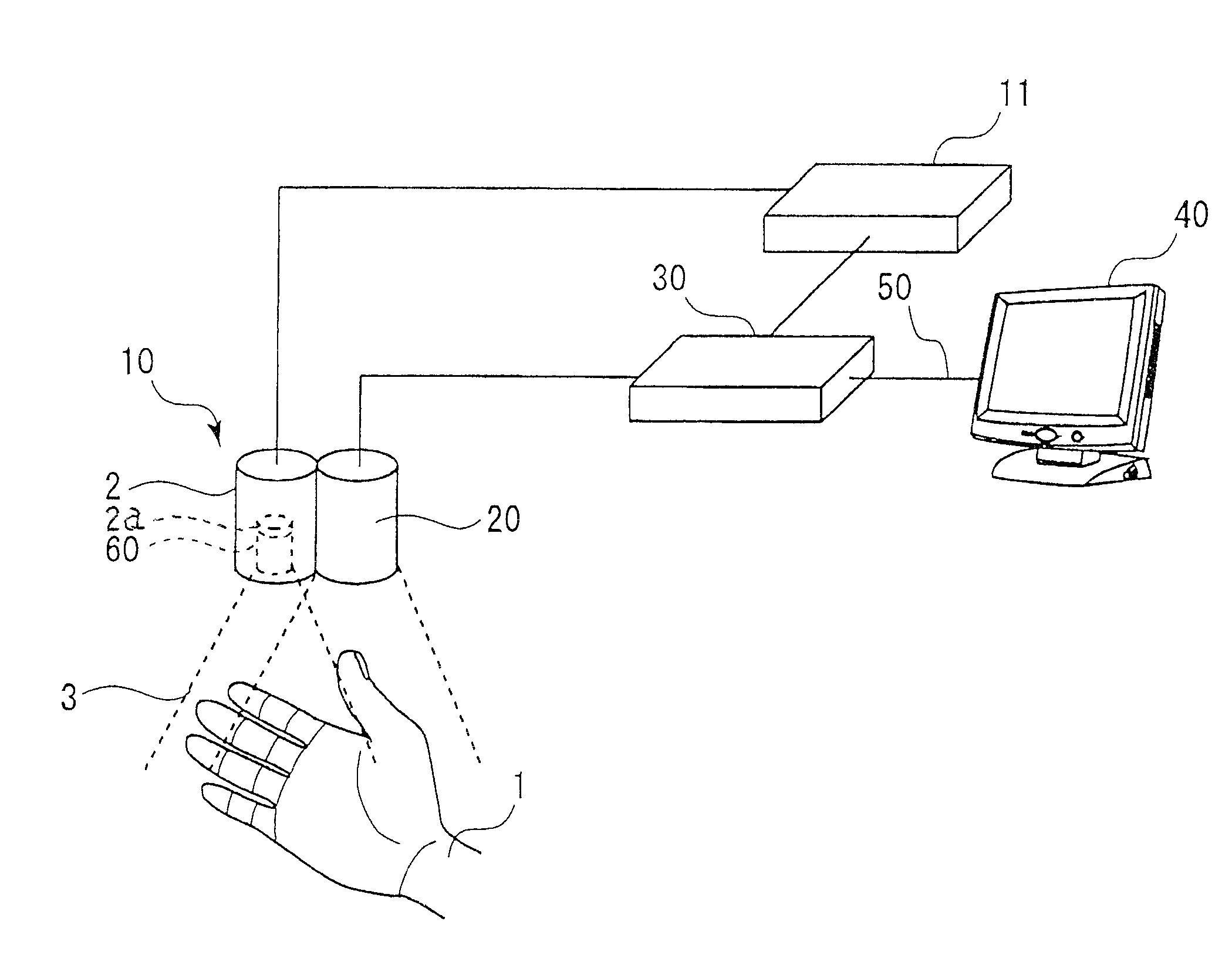
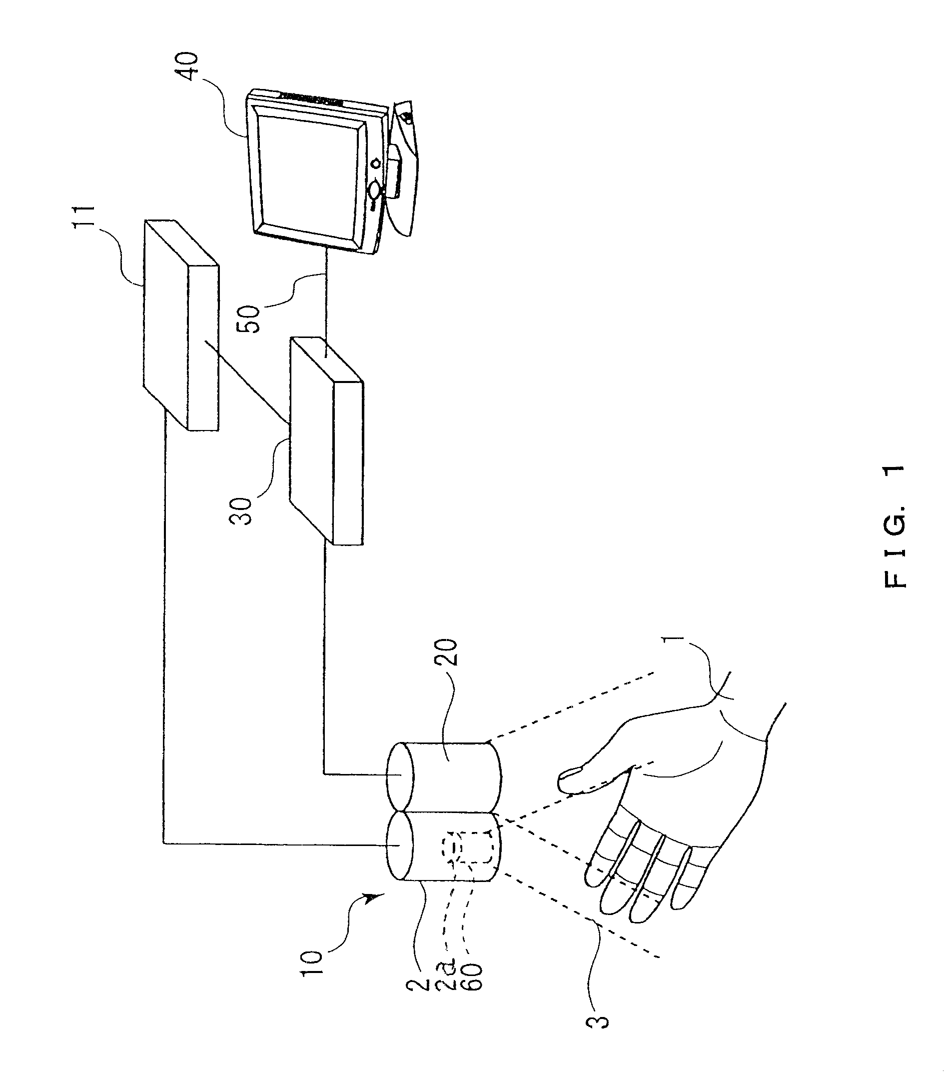
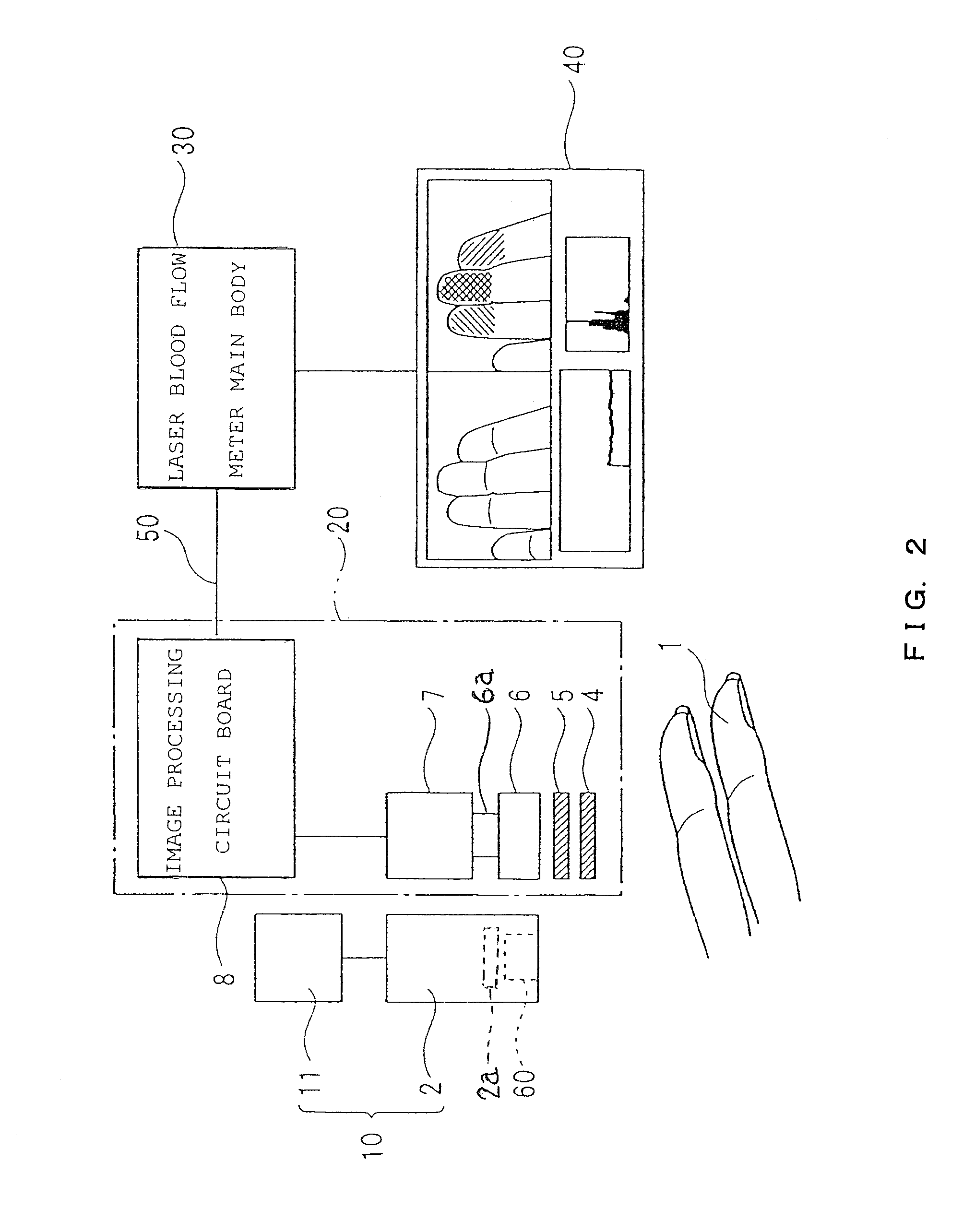
[0039] That is, as shown in FIGS. 1 and 2, the two-dimensional laser blood flow meter of this embodiment has laser light irradiating means 10 for irradiating laser light 3 of a predetermined wavelength to blood flows within a vital tissue 1, image capturing means 20 for capturing scattered light of the blood flow to which the laser light 3 has been irradiated, image processing means 8 for processing a captured image of the blood flows per pixel, value-of-blood flow calculating means (i.e., a laser blood flow meter main body) 30 for calculating the value of blood flow based on data per pixel and for processing as a color discernible image corresponding to ...


PUM


Abstract

Provided is a laser blood flow imaging apparatus whose configuration is simple and which has functions of arithmetically and concurrently processing blood flows of all points of measurement. The laser blood flow imaging apparatus includes: a laser light irradiating unit for irradiating laser light of a predetermined wavelength to a blood flow within a vital tissue; an image capturing unit for capturing scattered light from the blood flow irradiated with the laser light; an image processing unit for processing an image of the captured blood flow per pixel; a value-of-blood flow calculating unit for calculating a value of blood flow based on data per the pixel and for processing as a color discernible image corresponding to the calculated value; and a display unit for displaying the image of the blood flows processed by the value-of-blood flow calculating unit as a two-dimensional color image.

Description

BACKGROUND OF THE INVENTION [0001] 1. Field of the Invention [0002] The present invention relates to a technology of medical instrumentation, and more specifically, to a technology for inspecting a state of vital tissues by means of a blood flow meter utilizing laser light. [0003] 2. Description of the Related Art [0004] Oxygen and nutrition are supplied to vital tissues through blood flows. Specifically, they are supplied to the vital tissues substantially through microcirculation, and it is important to obtain information on blood flows thereof. There has been known a blood flow meter utilizing laser light as an instrument for measuring a state of blood flows. [0005] The blood flow meter (laser blood flow meter) utilizing laser light makes use of such characteristics of the laser light that frequency of the laser light scattered by red blood cells flowing within blood vessels is modulated while frequency of the laser light scattered by static tissues of the vital tissues is not mo...

Claims


Application Information

Patent Timeline
Patent Type & Authority Applications(United States)
IPC IPC(8): A61B5/02
CPCA61B5/0261
Inventor KASHIMA, SUSUMU
Owner OMEGAWAVE
Learn More