
Homogenization and heat-treatment of cast metals

a technology of heat treatment and metals, applied in the field of metal casting, can solve the problems of inability to meet the requirements of final product quality, so as to achieve the effect of reducing differences and allowing for modification of casting distan

Active Publication Date: 2007-05-10
NOVELIS INC
View PDF26 Cites 16 Cited by
  • Summary
  • Abstract
  • Description
  • Claims
  • Application Information

AI Technical Summary

Benefits of technology

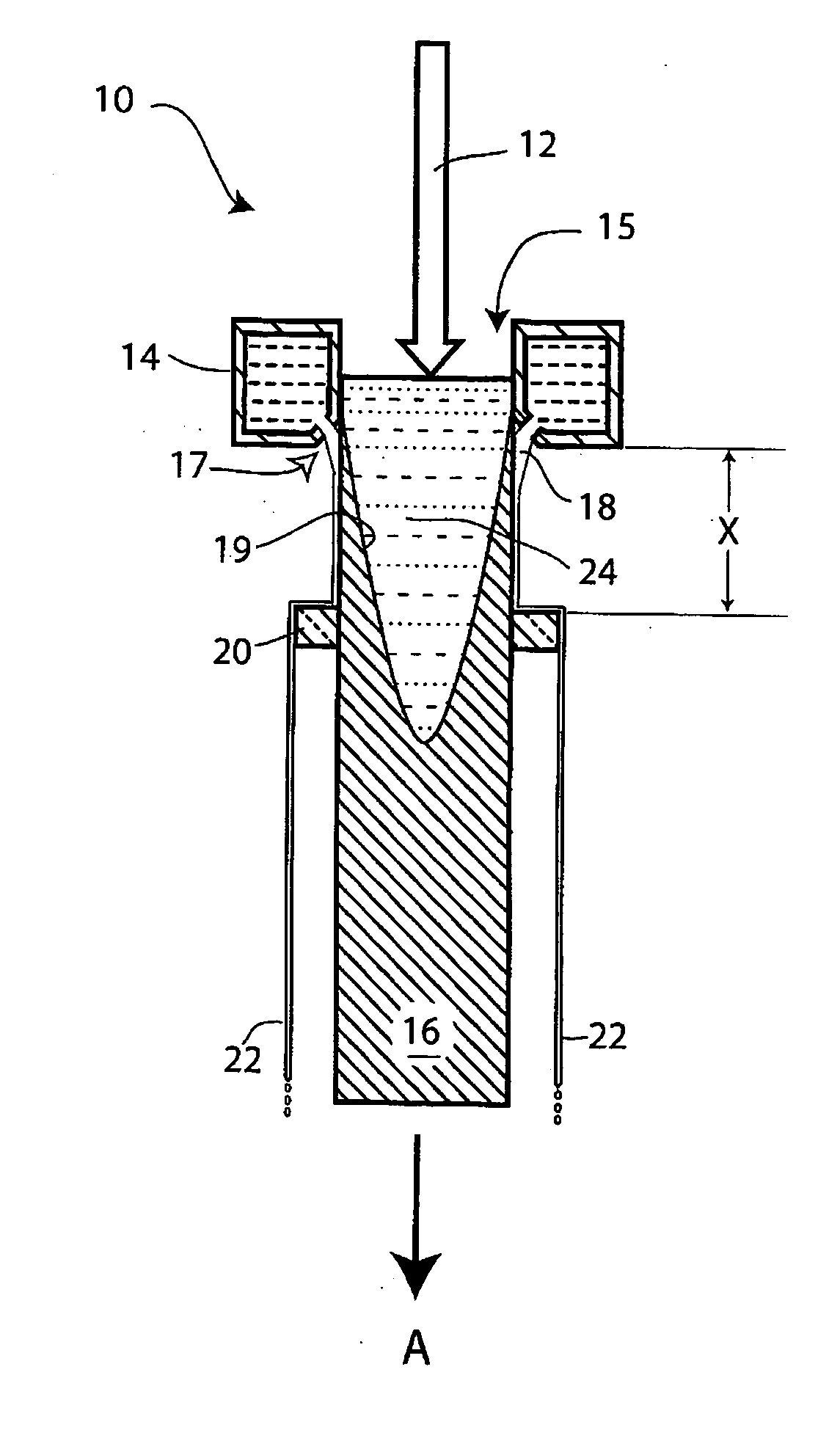
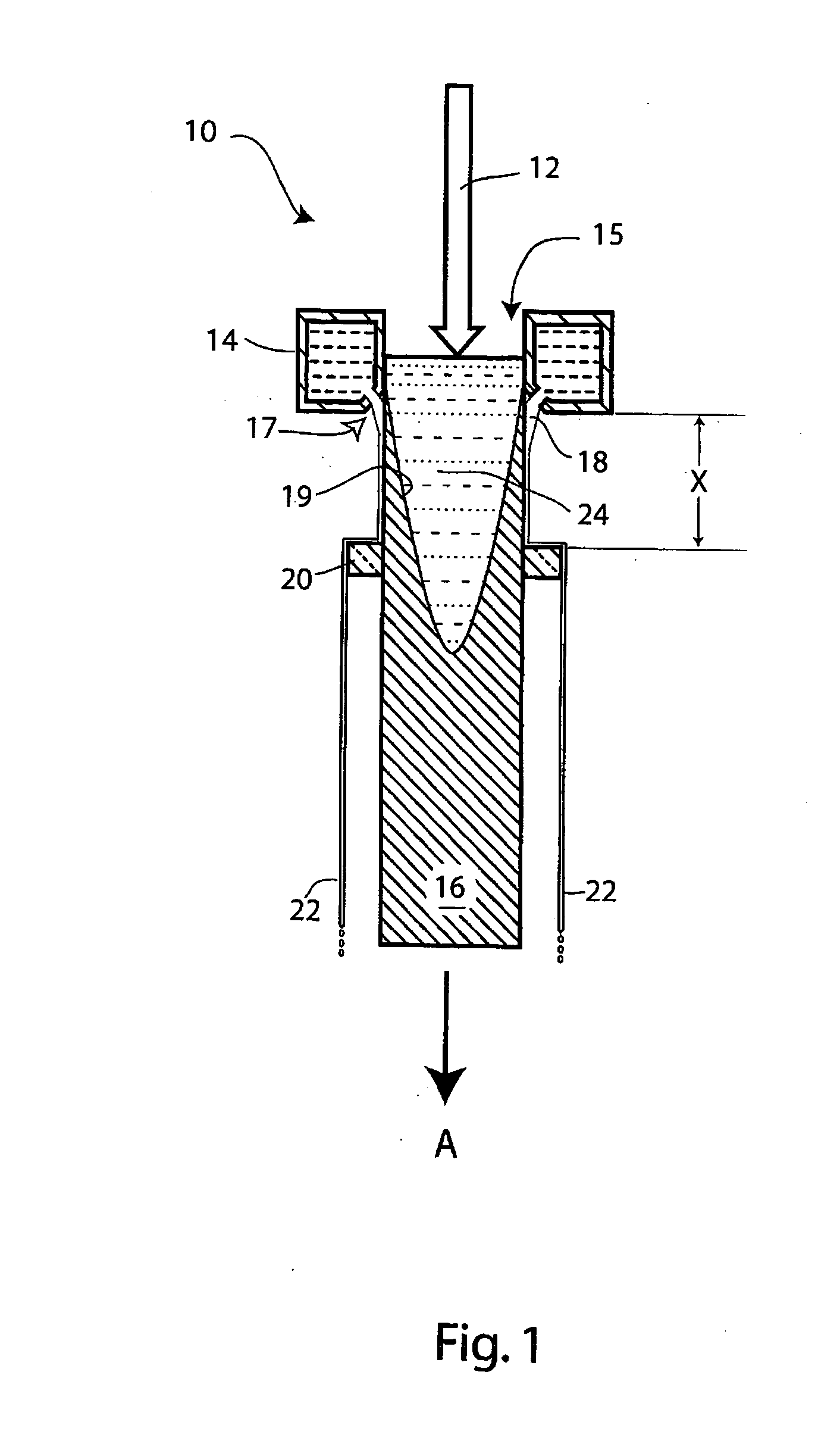
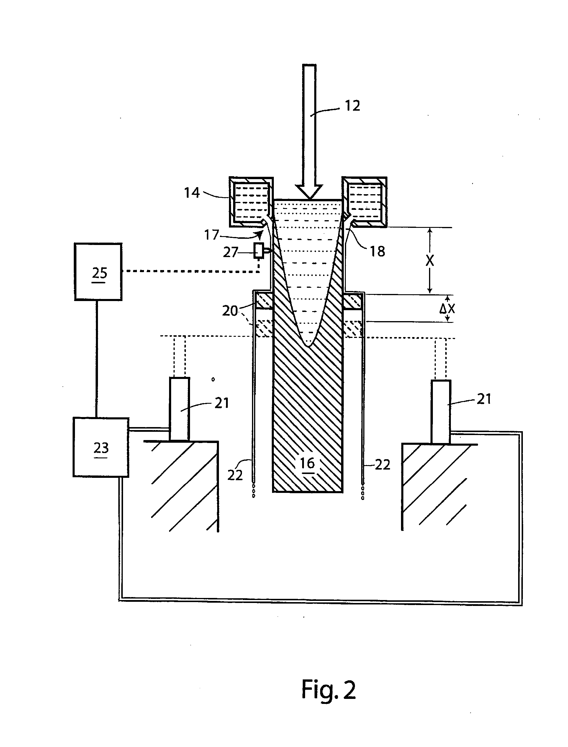
[0029] Surprisingly, desirable metallurgical changes can often be imparted in this way in a relatively short time (e.g. 10 to 30 minutes) and the procedure for achieving such a result can be incorporated into the casting operation itself, thereby avoiding the need for an additional expensive and inconvenient homogenizing step. Without wishing to be bound by any particular theory, it is possible that this is because desirable metallurgical changes are created or maintained as the alloy is being cast by a significant backward-diffusion effect (in either, or both, solid and liquid states and their combined ‘mushy’ form) for a short period of time rather than having undesirable metallurgical properties form during conventional cooling, that then require considerable time for correction in a conventional homogenization step.
[0051] (f) holding the ingot at that temperature for a period of time to allow continued diffusion of solute from the smaller (thermally-unstable) precipitates which enhance the growth of the larger more stable precipitates or, alternatively, gradually increasing the temperature, thereby increasing the solute concentration which contributes to growth with out requiring a temperature hold.

Problems solved by technology

The resulting structure of the metal is therefore quite complex and is characterized by compositional variances across not only the grain but also in the regions adjacent to the intermetallic phases where relatively soft and hard regions co-exist in the structure and, if not modified or transformed, will create final gauge property variances unacceptable to the final product.
Post-solidification cracks are caused by macroscopic stresses that develop during casting, which cause cracks to form in a trans-granular manner after solidification is complete.
Pre-solidification cracks are also caused by macroscopic stresses that develop during casting.
These defects render the ingot unacceptable for many purposes.

Method used


Image

  • Homogenization and heat-treatment of cast metals
  • Homogenization and heat-treatment of cast metals
  • Homogenization and heat-treatment of cast metals

Examples


example 1

[0134] Three direct chill cast ingots were cast in a 530 mm and 1,500 mm Direct Chill Rolling Slab Ingot Mold with a final length of greater than 3 meters. The ingots had an identical composition of A11.5% Mn; 6% Cu according to U.S. Pat. No. 6,019,939 (the disclosure of which is incorporated herein by reference). A first ingot was DC cast according to a conventional procedure, a second was DC cast with in-situ homogenization according to the procedure shown in FIGS. 7 and 8, where the coolant is removed and the ingot is allowed to cool to room temperature after being removed from the casting pit, and the third was DC cast with in-situ quench homogenization according to the procedure of FIG. 9, where the coolant is removed from the surface of the ingot and the ingot is allowed to reheat then quench in a pit of water approximately one meter below the mold.

[0135] In more detail, FIG. 7 shows the surface temperature and the center (core) temperature over time of an Al—Mn—Cu alloy as i...

example 2

[0157] An Al-4.5% Cu ingot was cast according to the invention and the ingot was cooled (quenched) at the end of the cast. FIG. 20 is and SEM with Copper (Cu) Line Scan of the resulting ingot. The absence of any coring of Copper in the unit cell is to be noted. Although the cells are slightly larger than those of FIG. 16, there is a reduced amount of cast intermetallic at the intersection of the unit cells and the particles are rounded.

[0158]FIG. 21 shows the thermal history of the casting of the ingot illustrating the final quench at the end of the cast. The convergence temperature (452° C.) in this case is below the solvus for the composition chosen, but desirable properties are obtained.

example 3

[0160] An ingot of an Al-0.5% Mg-0.45% Si alloy (6063) was cast according to a process as illustrated in the graph of FIG. 23. This shows the thermal history in the region where solidification and reheat takes place in a case where the bulk of the ingot is not forcibly cooled.

[0161] The same alloy was cast under the conditions shown in FIG. 24 (including a quench). This shows the temperature evolution of an ingot where the surface and core temperatures converged at a temperature of 570° C., and which is then forcibly cooled to room temperature. This can be compared to the procedure shown in FIG. 8 which involved a high rebound temperature and slow cooling, which is desirable when a more rapid correction of the cellular segregation is needed, or when the alloy contains elements that diffuse at a slow pace. The use of a high rebound temperature (considerably above the solvus of the alloy), held for a prolonged period of time, allows elements near the grain boundary to diffuse quite q...


PUM

PropertyMeasurementUnit
Temperatureaaaaaaaaaa

Abstract

A method of casting a metal ingot with a microstructure that facilitates further working, such as hot and cold rolling. The metal is cast in a direct chill casting mold, or the equivalent, that directs a spray of coolant liquid onto the outer surface of the ingot to achieve rapid cooling. The coolant is removed from the surface at a location where the emerging embryonic ingot is still not completely solid, such that the latent heat of solidification and the sensible heat of the molten core raises the temperature of the adjacent solid shell to a convergence temperature that is above a transition temperature for in-situ homogenization of the metal. A further conventional homogenization step is then not required. The invention also relates to the heat-treatment of such ingots prior to hot working.

Description

CROSS-REFERENCE TO RELATED APPLICATIONS [0001] This application claims the priority rights of our prior U.S. provisional patent application Ser. Nos. 60 / 731,124 filed Oct. 28, 2005, 60 / 733,943 filed Nov. 3, 2005 and 60 / 794,600 filed Apr. 25, 2006. The disclosures of each of these prior applications are specifically incorporated herein by reference.BACKGROUND OF THE INVENTION [0002] I. Field of the Invention [0003] This invention relates to the casting of metals, particularly metal alloys, and their treatment to make them suitable to form metal products such as sheet and plate articles. [0004] II. Background Art [0005] Metal alloys, and particularly aluminum alloys, are often cast from molten form to produce ingots or billets that are subsequently subjected to rolling, hot working, or the like, to produce sheet or plate articles used for the manufacture of numerous products. Ingots are frequently produced by direct chill (DC) casting, but there are equivalent casting methods, such as...

Claims


Application Information

Patent Timeline
IPC IPC(8): B22D11/124B22D11/22B22D11/049
CPCB22D11/003B22D11/049B22D11/1248B22D11/22Y10T29/49988B22D27/04C22F1/04Y10T29/49991B22D11/225B22D11/124B22D11/055B22D7/00B22D30/00B22D15/04B22D21/04
Inventor WAGSTAFF, ROBERT BRUCEFENTON, WAYNE J.
Owner NOVELIS INC
Learn More