Organic light emitting display

Active Publication Date: 2007-05-10
AU OPTRONICS CORP
View PDF13 Cites 8 Cited by
  • Summary
  • Abstract
  • Description
  • Claims
  • Application Information

AI Technical Summary

Benefits of technology

[0008] According to the claimed invention, a method to improve the contrast ratio of the OLED is provided. The OLED comprises a first substrate, a second substrate parallel and opposite to the first substrate, having a plurality of sub-pixels, a plurality of organic emitting elements and an antireflective layer in each of the sub-pixels, wherein the ratio of the area of the antireflective layer to the area of the sub-pixel is defined as the anti-reflect/sub-pixel ratio. This method comprises determining a first relation equation between the relative life time of the organic emitting elements and the anti-reflect/sub-pixel ratio based on the characteristics of the organic emitting elements, and then determining a second relation equation between the contrast ratio of the OLED and the anti-reflect/sub-pixel ratio based on the characteristics of the OLED. Then, a predetermined minimum value of the contrast ratio and a predetermined minimum value of the relative life time value are chosen to be used in the first relation equation and the second rel

Problems solved by technology

Since the conductors, electrodes, or other patterns made of metal in the OLED may reflect lights, its display images often has low quality caused by its unfavorable contrast ratio when the OLED is operated in an environment with strong ambient light.
However, although the polarizer may reduce the reflection of the ambient light effectively, at the mean time the penetration rate of the light produced by the OLED itself may be reduced to 42%, which causes the insufficient luminous efficiency.
In addition, to compensate the deficient br

Method used


Image

  • Organic light emitting display
  • Organic light emitting display
  • Organic light emitting display

Examples


Example

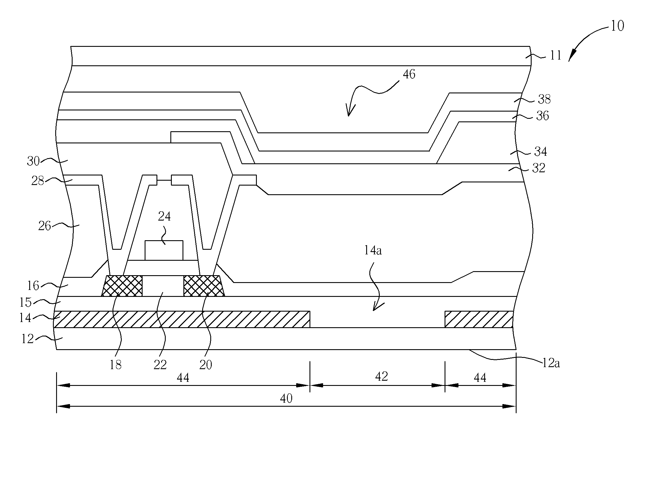
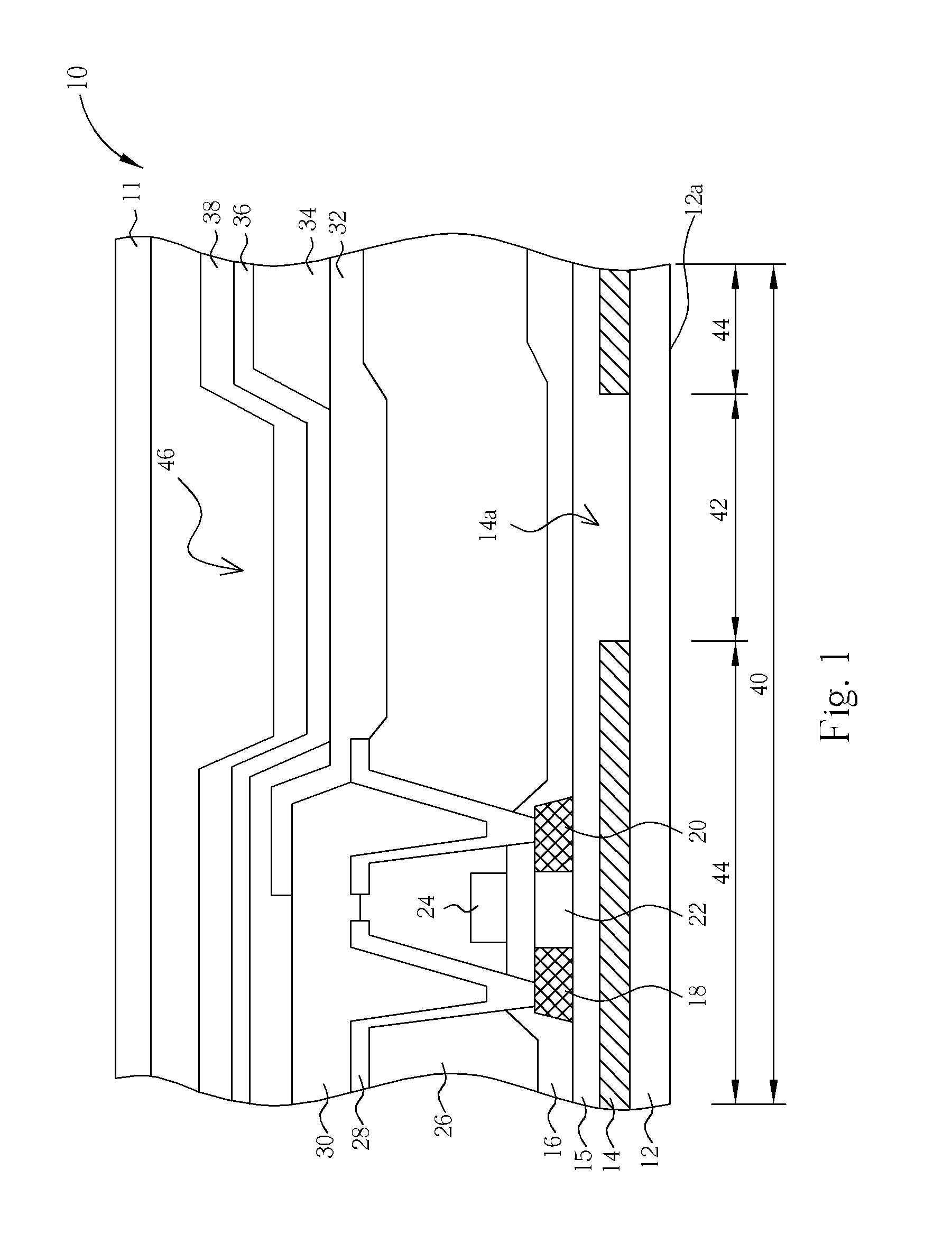
[0014] Please refer to FIG. 1. FIG. 1 is a side cross-section schematic diagram of an OLED 10 of this invention. In this figure, only one single sub-pixel 40 was shown and used for explanation. As shown in FIG. 1, the OLED 10 of this invention comprises a first substrate 11 and a second substrate 12, wherein the first substrate 11 and the second substrate 12 are parallel to each other and jointed by sealant (not shown in the figure) to maintain a fixed spacing between them. According to this embodiment, the OLED 10 is a rear emission type panel. Therefore, the surface 12a of the second substrate 12 facing away from the first substrate 11 is the display surface 12a of the OLED 10. The second substrate 12 is made of transparent materials such as glass, plastic, quartz, or other transparent materials. The first substrate 11 may be made of either transparent materials or non-transparent materials. The second substrate 12 comprises a plurality of sub-pixels 40, each of which comprises an...


PUM


Abstract

An OLED has a first substrate, a second substrate, a plurality of organic emitting elements positioned in each sub-pixel, and an antireflective layer. The ratio of the area of the antireflective layer to that of the sub-pixel is between about 60% to about 87%.

Description

BACKGROUND OF THE INVENTION [0001] 1. Field of the Invention [0002] This invention relates to an organic light emitting display (OLED), and more particularly, to an OLED with a high contrast ratio on the display screen and a longer life time. [0003] 2. Description of the Prior Art [0004] In various types of flat panel displays, since an OLED, being developed later than a liquid crystal display (LCD), has many beneficial characteristics, such as having a spontaneous light source, a wide viewing angle, high response velocity, power saving, strong contrast, high brightness, small thickness, full-color, simpler structure, and a wide operating temperature, the OLED has been used extensively in small and medium scale portable display fields. After continuous research and development by manufacturers and scholars, the break through of some unresolved problems, such as low yield rate, unsatisfied mask application, unstable cap seal, has provided eminent progress. [0005] Since the conductors...

Claims


Application Information

Patent Timeline
IPC IPC(8): H01J1/62H01J63/04
CPCH01L27/3244H01L51/5284H10K59/12H10K50/865
Inventor LI, SHI-HAO
Owner AU OPTRONICS CORP
Why Eureka
Try Eureka