
Reduced Rating T-Connected Autotransformer For Converting Three Phase AC Voltages To Nine/Six Phase Shifted AC Voltages

Inactive Publication Date: 2007-05-10
INDIAN INST OF TECH
View PDF5 Cites 9 Cited by
  • Summary
  • Abstract
  • Description
  • Claims
  • Application Information

AI Technical Summary

Benefits of technology

[0007] Thus, one object of the invention is to provide an autotransformer that results in reduction in number of coils on the transformer.
[0008] Another object of the invention is to achieve the reduction in rating of magnetics, resulting in saving in cost.
[0009] One other object of the invention is to provide a single transformer that can be used either as a step up transformer or step-down transformer or a unity gain transformer. This feature enables a manufacturer to provide a single transformer that can be used in different applications, only by choosing different taps. This results in reduction in design and manufacturing cost as only a single autotransformer has to be designed and manufactured instead of two different autotransformers.
[0010] Yet, another objective is to provide a transformer which performs well even during load variation on the dc side.

Problems solved by technology

These power processors generally use non-linear devices such as diode, thyristor, IGBT etc., which results in injection of current harmonics, resulting in equipment overheating, low rectifier efficiency, malfunction of sensitive electronic equipments and the like.
These harmonic currents result in voltage distortion (as they travel through finite source impedance) at Point of Common Coupling (PCC), thereby affecting the nearby consumers.
But it is very difficult to build wye and delta connected windings with comparable electrical characteristics (voltage and impedance).
This results in higher dc-link voltage by about 14%, making the scheme non applicable for retrofit applications.

Method used


Image

  • Reduced Rating T-Connected Autotransformer For Converting Three Phase AC Voltages To Nine/Six Phase Shifted AC Voltages
  • Reduced Rating T-Connected Autotransformer For Converting Three Phase AC Voltages To Nine/Six Phase Shifted AC Voltages
  • Reduced Rating T-Connected Autotransformer For Converting Three Phase AC Voltages To Nine/Six Phase Shifted AC Voltages

Examples


Embodiment Construction

[0059] In relation to the drawings, exemplary embodiments of the present invention are described in the following detailed description. However, it will be apparent to a person skilled in the art that numerous other equivalent embodiments or ways of practicing the present invention exist.

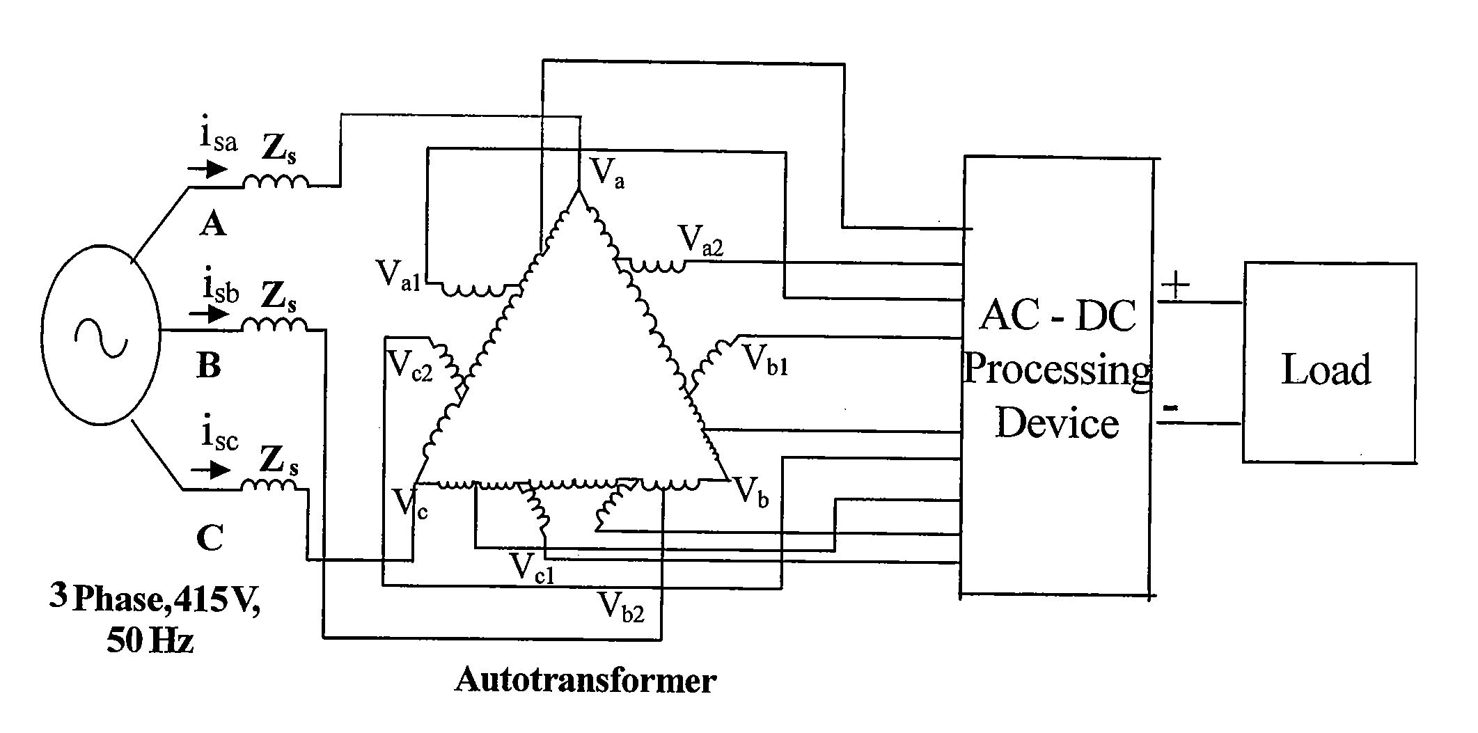
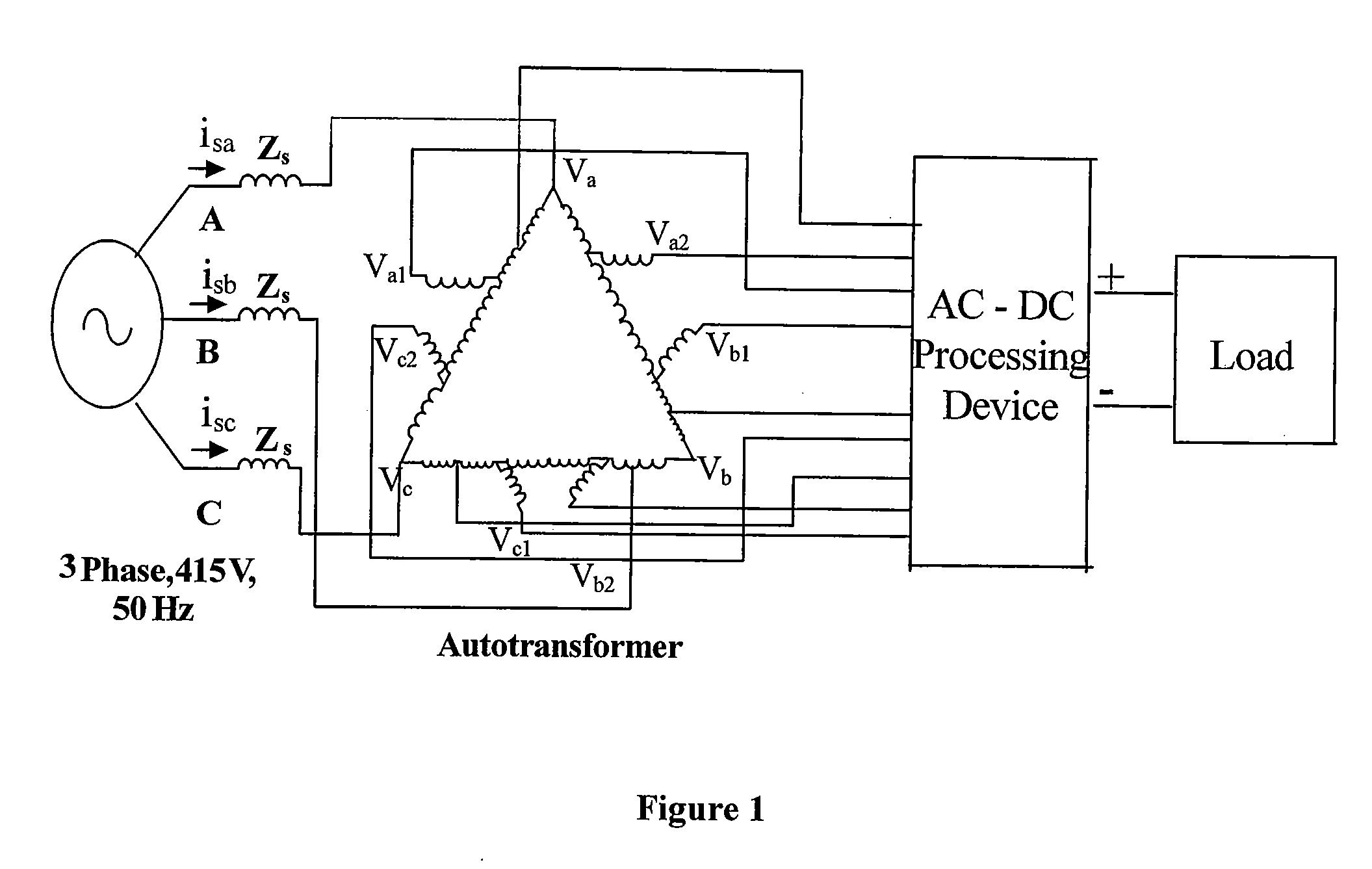
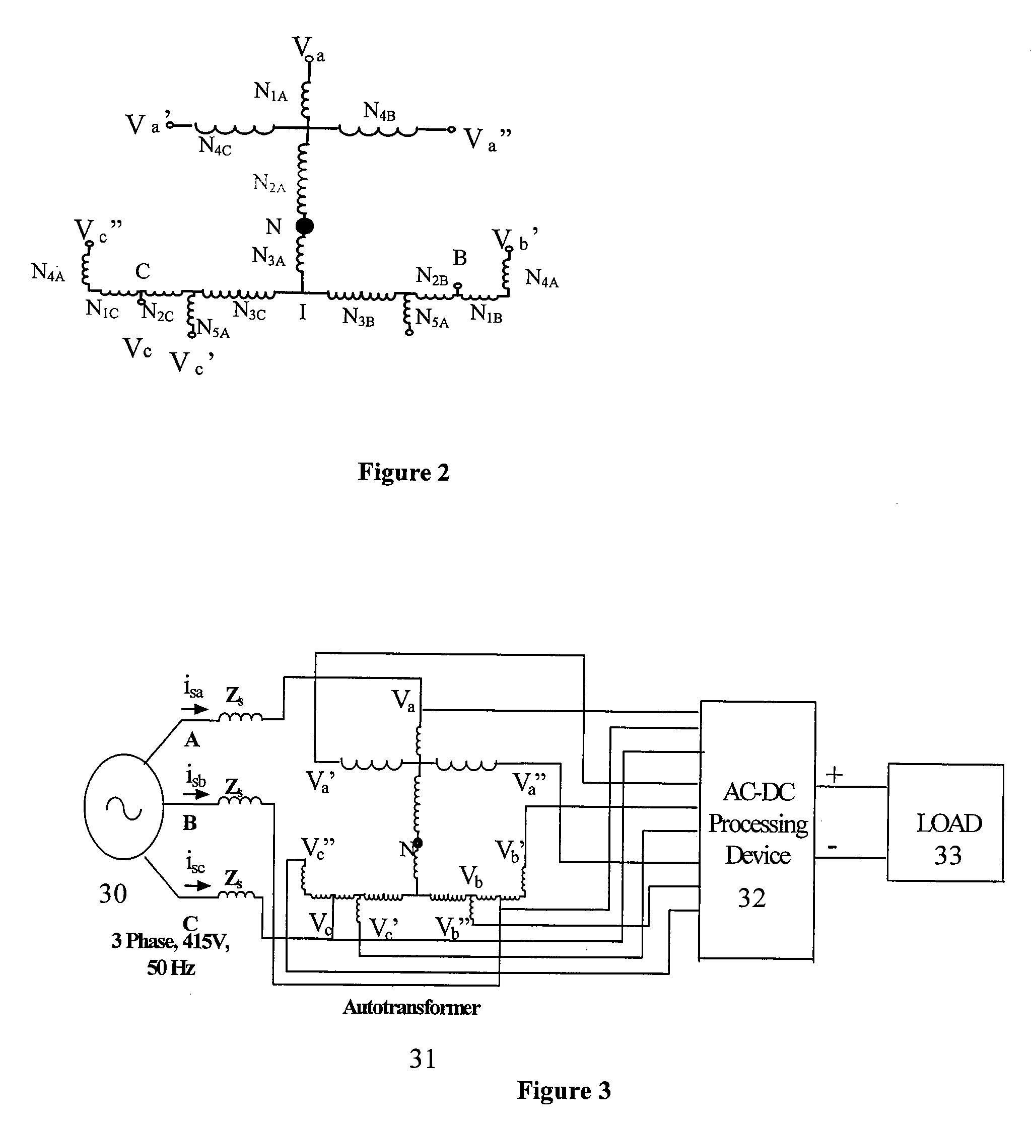
[0060] The design procedure used in the invention will be explained for T-connected autotransformer based 18-pulse AC-DC converter and 12-pulse AC-DC converter. It will be appreciated by a person skilled in the art that the scope of the invention is not limited to 18-pulse AC-DC converter or 12-pulse AC-DC converter.

[0061] Conventionally, the 18-pulse AC-DC conversion may be achieved by having three sets of balanced 3-phase line voltages, which are either ±20° or ±40° out of phase with respect to each other, and the magnitude of these line voltages should be equal to each other. The minimum phase shift required for proper harmonic elimination is computed by: Phase shift=60° / Number of six-pulse con...


PUM


Abstract

The invention provides a T-connected autotransformer for converting three-phase ac input voltages to nine phase shifted ac voltages feeding three sets of three-phase diode rectifier bridges. The nine phase shifted voltages are at an angle of +20 degree or −20 degree with respect to the supply voltages and their magnitudes are essentially identical. The present design requires substantially fewer coils than other autotransformers for 18-pulse AC-DC converters, resulting in saving in space, volume, weight, size and cost of the converter. The magnetics requirement is only about 30% of the drive rating. The output voltage ratio can also be selected to give an average dc output from the proposed converter same as that of a conventional three-phase diode bridge rectifier. However, it is also possible to step up or step down the output voltage as required.

Description

FIELD OF THE INVENTION [0001] The present invention relates to an autotransformer for converting three phase ac voltages to nine / six phase shifted voltages, which can be used for harmonic reduction in different applications such as adjustable speed AC or DC motor drives. BACKGROUND OF THE INVENTION [0002] With the revolution in semiconductor self-commutating devices and reduction in their cost, most of the electric utilities in industrial, commercial, residential, aerospace environments make use of some kind of power processors. These power processors are being used in applications such as Heating, Ventilation and Air Conditioning (HVAC) systems, pumps, blowers, fans, paper and textile mills, rolling mills and the like. These power processors generally use non-linear devices such as diode, thyristor, IGBT etc., which results in injection of current harmonics, resulting in equipment overheating, low rectifier efficiency, malfunction of sensitive electronic equipments and the like. Th...

Claims


Application Information

Patent Timeline
IPC IPC(8): G05F1/14
CPCH01F30/02H01F30/14H02M5/14
Inventor SINGH, BHIMBHUVANESHWARI, G.GARG, VIPIN
Owner INDIAN INST OF TECH
Learn More