Matrix decoder

Inactive Publication Date: 2007-05-10
NOVATEK MICROELECTRONICS CORP
View PDF2 Cites 18 Cited by
  • Summary
  • Abstract
  • Description
  • Claims
  • Application Information

AI Technical Summary

Benefits of technology

[0008] Accordingly, the present invention is directed to provide a matrix decoder, which is applicable to the gate driver of an LCD panel. The number of high voltage MOSFETs can be reduced greatly, so as to minimize the surface area of the circuit, without affecting t

Problems solved by technology

Since the level shifters and the output stages require high voltage process, and the numbers thereof are the same as that of the output terminals of the gate driver, t

Method used


Image

  • Matrix decoder
  • Matrix decoder
  • Matrix decoder

Examples


Embodiment Construction

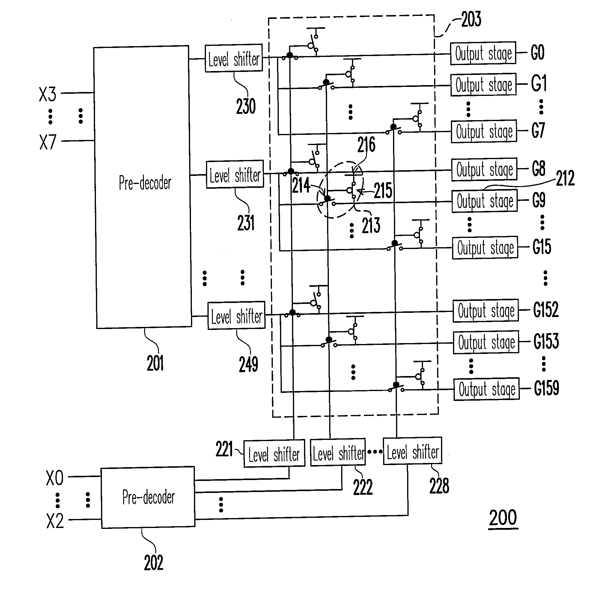
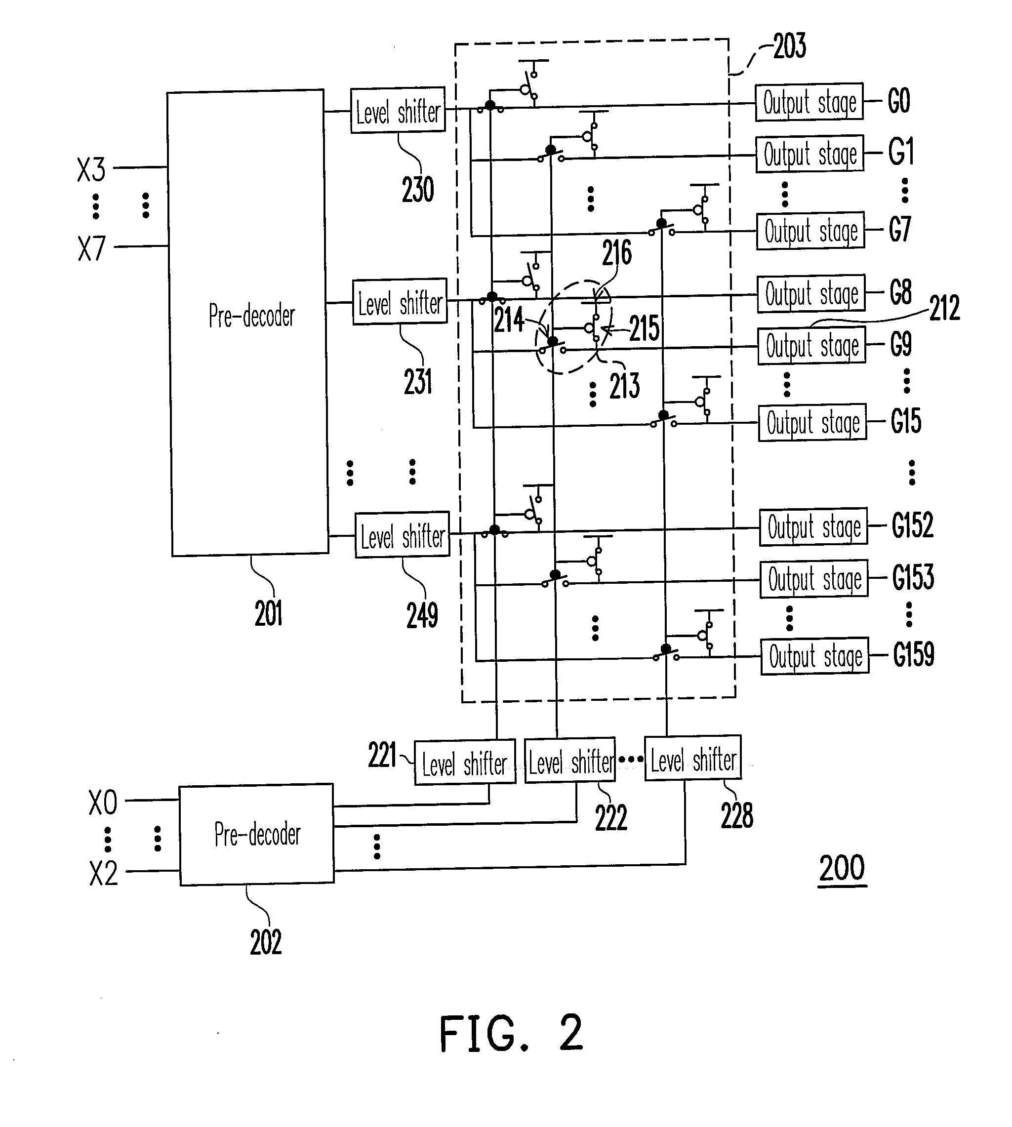
[0022] Generally, when a typical gate driver is under normal operation, only one gate line thereof will output logic I while the other gate lines thereof output logic 0. Thus, at any time, only one level shifter and one output stage are in action. In the present invention, the original decoder and the control signals thereof are divided into two sections based on this characteristic of the gate driver.

[0023]FIG. 2 is a schematic block diagram of a matrix decoder 200 according to an embodiment of the present invention. The matrix decoder 200 is a portion of the gate driver of an LCD panel, which includes pre-decoders 201 and 202, 28 level shifters (230˜249, 221˜228), a demultiplexer 203, and 160 output stages (e.g. output stage 212). The pre-decoders 201 and 202 are formed by low voltage components; the level shifters 230˜249 and 221˜228 include low, middle, and high voltage components, wherein most components are high voltage components; and the demultiplexer 203 and the output sta...


PUM


Abstract

A matrix decoder is provided, which includes a plurality of first level shifters, a plurality of second level shifters, and a demultiplexer. The first level shifters and the second level shifters boost the voltages of inputted signals to the voltages required by high voltage components and output the boosted signals. One of the first level shifters receives a first logic state and outputs a fifth logic state. Each of the other first level shifters receives a second logic state and outputs a sixth logic state. One of the second level shifters receives a third logic state and outputs a seventh logic state. Each of the other second level shifters receives a fourth logic state and outputs an eighth logic state. The demultiplexer outputs a ninth logic state and a plurality of tenth logic states according to the logic states outputted by the first level shifters and the second level shifters.

Description

CROSS-REFERENCE TO RELATED APPLICATION [0001] This application claims the priority benefit of Taiwan application serial no. 94138720, filed Nov. 4, 2005. All disclosure of the Taiwan application is incorporated herein by reference. BACKGROUND OF THE INVENTION [0002] 1. Field of Invention [0003] The present invention relates to a matrix decoder. More particularly, the present invention relates to a matrix decoder including level shifters. [0004] 2. Description of Related Art [0005]FIG. 1 is a schematic block diagram of a conventional gate driver 100 which is applicable to a liquid crystal display panel. The decoder 101 has a plurality of output terminals, each output terminal is coupled with a level shifter and an output stage and is eventually coupled to one of the gate lines G1˜Gm. [0006] The decoder 101 receives control signals X0˜Xn, and the control signals X0˜Xn indicate which gate line is to be turned on. For example, if the gate line G1 is to be turned on, the decoder 101 outp...

Claims


Application Information

Patent Timeline
IPC IPC(8): H03M7/00
CPCG09G3/3674G09G2330/04
Inventor LIU, SHANG-I
Owner NOVATEK MICROELECTRONICS CORP
Why Eureka
Try Eureka