Signal detecting device and method for inductive load

a signal detection and inductive load technology, applied in the direction of electric generator control, pulse technique, instruments, etc., can solve the problems of increasing the scale of a/d converter circuits and i/o circuits, increasing costs, and malfunctions, and achieves simple construction and efficient detection of plural signals.

Active Publication Date: 2007-05-10
DENSO CORP
View PDF11 Cites 15 Cited by
  • Summary
  • Abstract
  • Description
  • Claims
  • Application Information

AI Technical Summary

Benefits of technology

[0005] An object of the present invention is to efficiently detect plural signals generated during operation of a load driving apparatus for driving inductive loads, with a simple construction.

Problems solved by technology

However, an attempt to monitor many detection parameters by using a CPU as in the above technologies to detect an abnormality in equipment inevitably results in increasing the scale of A / D converter circuits and I / O circuits.
Accordingly, the sizes of elements such as a microcomputer including a CPU increase, leading to an increase in cost.
In the case of detecting an abnormality in equipment used in relatively hot environments such as an electric power generator mounted in a vehicle, malfunction may occur due to a leak current of circuit elements.
Furthermore, circuits mounted in a vehicle are required to have very high reliability, and an increase in the circuit size would adversely affect the reliability.

Method used


Image

  • Signal detecting device and method for inductive load
  • Signal detecting device and method for inductive load
  • Signal detecting device and method for inductive load

Examples


Embodiment Construction

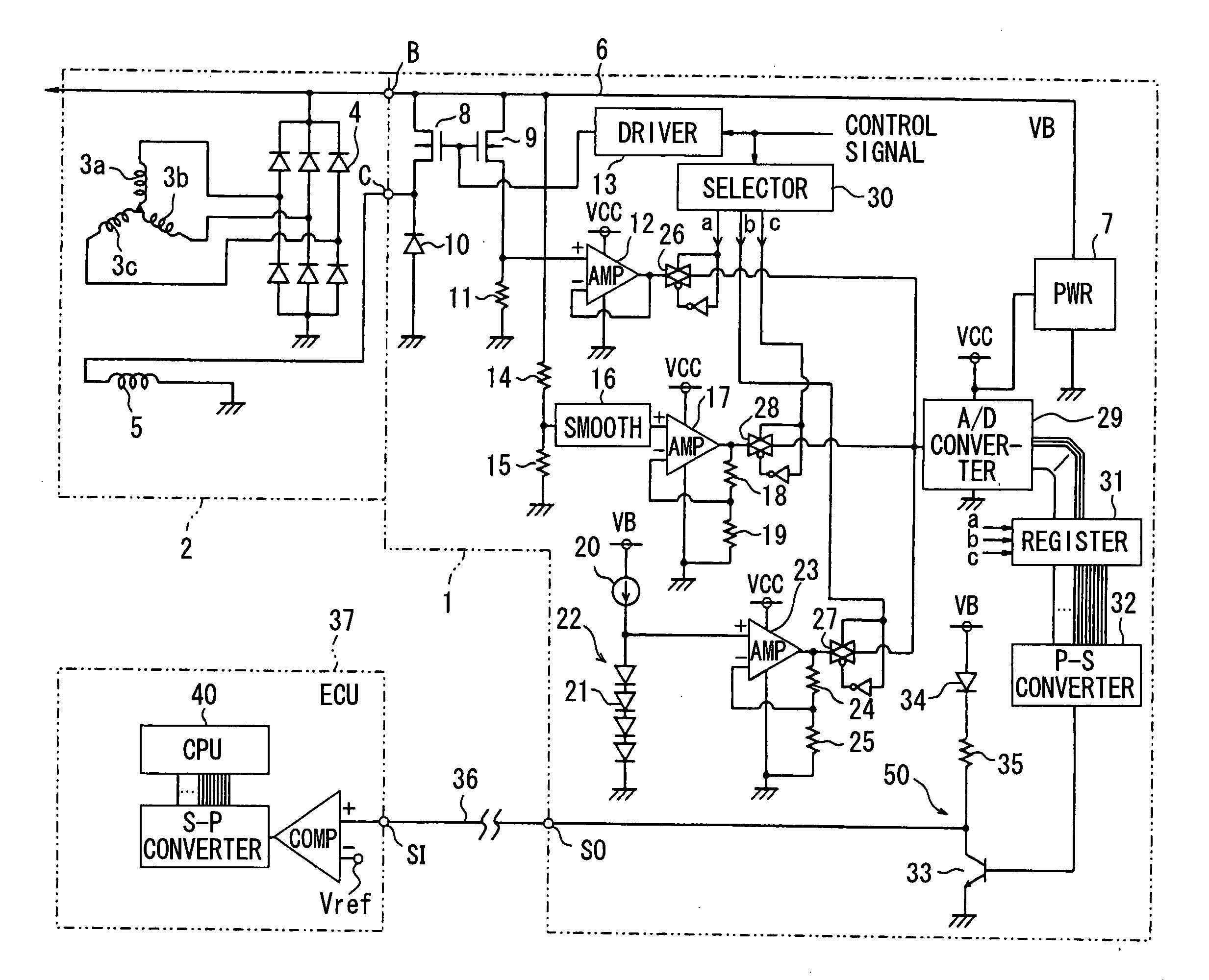
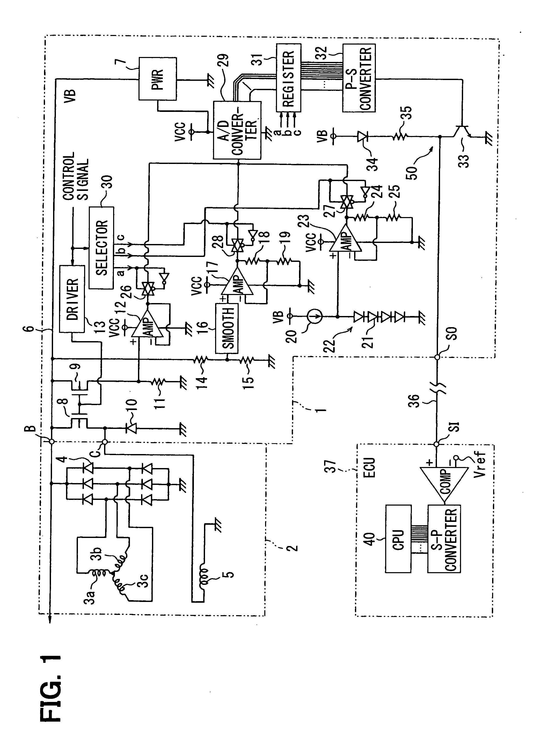
[0015] Referring to FIG. 1, a vehicle electric power generator system includes a regulator 1 as a load driving apparatus and signal detecting device, and a vehicle electric power generator (alternator) 2. The regulator 1 is provided to control a voltage of an output terminal (B-terminal) of the vehicle generator 2 so that it becomes equal to a predetermined regulation voltage setting value (e.g., 14V).

[0016] The vehicle generator 2 comprises: three-phase stator coils 3a, 3b, 3c included in a stator; a rectifying circuit 4 provided to rectify a full wave on three-phase outputs of these stator coils 3a to 3c; and an exciting coil 5 (inductive load) included in a rotor. The vehicle generator 2 is rotationally driven by an engine of a vehicle (not shown). Its output voltage control is performed by the regulator 1 by intermitting, that is, alternately turning on and off, an electric current to the exciting circuit 5. The output terminal (B-terminal) of the generator 2 is connected to a ...


PUM


Abstract

A signal detecting device detects, as analog voltage signals, a current flowing through an exciting coil of an electric power generator, a source voltage and a temperature of a regulator that change as a current is fed to the exciting coil by an FET. These analog voltage signals are subjected to A/D conversion by a single A/D converter circuit. The detected current is subjected to A/D conversion in a period during which the FET is ON, while the detected source voltage and the detected temperature are subjected to A/D conversion in a period during which the FET is OFF.

Description

CROSS REFERENCE TO RELATED APPLICATION [0001] This application is based on and incorporates herein by reference Japanese Patent Application No. 2005-277796 filed on Sep. 26, 2005. FIELD OF THE INVENTION [0002] The present invention relates to a signal detecting device and method used in a load driving apparatus that controls a current to an inductive load by alternately turning on and off the current supply by a switching element to drive the load. BACKGROUND OF THE INVENTION [0003] JP-2002-171688A discloses A / D conversion of currents fed to coils of a charging generator. Further U.S. Pat. No. 5,521,486 (JP-7-184330A) and JP-6-70599A disclose A / D conversion of currents and other parameters in an electric power generator to monitor an abnormality by a CPU. [0004] However, an attempt to monitor many detection parameters by using a CPU as in the above technologies to detect an abnormality in equipment inevitably results in increasing the scale of A / D converter circuits and I / O circuits...

Claims


Application Information

Patent Timeline
Patent Type & Authority Applications(United States)
IPC IPC(8): H01H47/00G01R19/00H02P9/30H02P25/098H02P29/00H02P29/60H02P101/25H02P101/45H02P103/20
CPCH02P9/305
Inventor ASADA, TADATOSHIUEDA, SUSUMU
Owner DENSO CORP
Why Eureka
Try Eureka