Dynamic bearing device

a bearing device and bearing technology, applied in sliding contact bearings, record information storage, instruments, etc., can solve problems such as a reduction in bearing rigidity, especially in thrust directions, and achieve the effects of reducing impact load, ensuring strength and rigidity, and reducing the weight of axial members

Inactive Publication Date: 2007-05-10
NTN CORP
View PDF6 Cites 13 Cited by
  • Summary
  • Abstract
  • Description
  • Claims
  • Application Information

AI Technical Summary

Benefits of technology

[0011] In the above structure, the axial member can have a structure in which an outer circumference of the axial part is formed of a hollow cylindrical metal material and a core of the axial part and the flange part are formed of a resin integrally with each other. By forming the outer circumference of the axial part by a metal material, it is possible to ensure strength and rigidity that are required for the axial member, as well as abrasion resistance of the axial part with respect to a metal bearing sleeve formed of a sintered metal or the like. Moreover, since many parts of the axial member (the core of the axial part and the flange part) are formed of a resin, the weight of the axial member can be reduced. Thus, it is possible to reduce impact load when the axial member collides with other bearing components (the bearing sleeve, the bottom of the housing, or the like) and to avoid generation of a flaw or damage due to the collision. In addition, since the flange part is formed of a resin and has small sliding friction, it is possible to reduce a friction coefficient between the flange part and the other bearing component facing the flange part.
[0012] A motor including the aforementioned dynamic bearing device, a rotor magnet, and a stator coil has high thrust bearing rigidity at high temperatures and a low torque at low temperatures, and also has a feature of a low cost.

Problems solved by technology

In a general dynamic bearing device, because of decrease of viscosity of fluid (oil) at high temperatures, decrease of bearing rigidity, especially in a thrust direction is a problem.
As described above, the conventional structure has a drawback that the difference of the amount of thermal expansion between the flange part and the housing acts to aid the aforementioned problems both at high temperatures and at low temperatures.

Method used


Image

  • Dynamic bearing device
  • Dynamic bearing device
  • Dynamic bearing device

Examples


Embodiment Construction

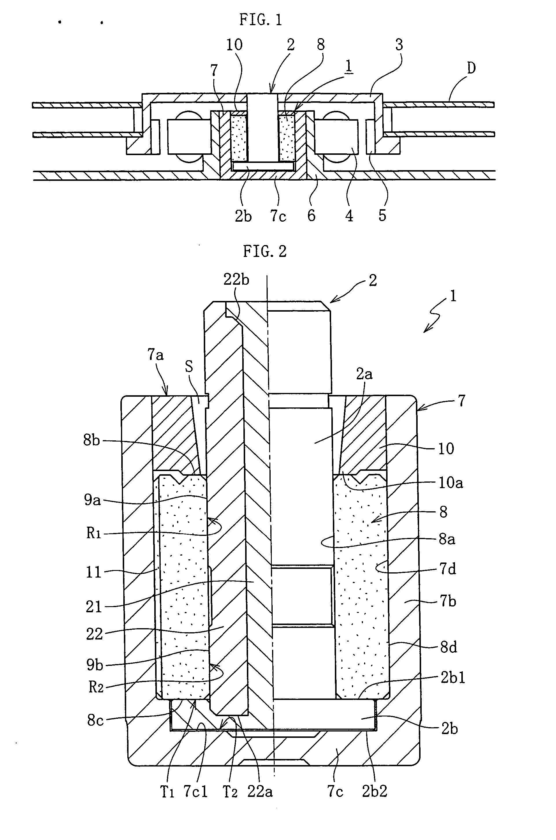
[0018] Embodiments of the present invention will now be described hereinafter with reference to FIGS. 1 through 5.

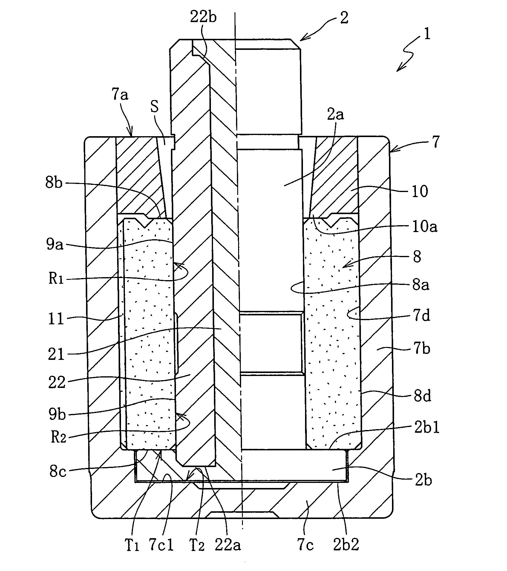
[0019]FIG. 1 shows an exemplary structure of a spindle motor for information equipment, in which a dynamic bearing device 1 according to an embodiment of the present invention is incorporated. This spindle motor is used in a disk driving device such as an HDD, and includes a dynamic bearing device 1 that supports an axial member 2 in a non-contact manner to be freely rotatable, a disk hub 3 attached to the axial member 2, and a stator coil 4 and a rotor magnet 5 that are arranged to be opposed with each other with a gap in a radial direction interposed therebetween. The stator coil 4 is attached to an outer circumference of a bracket 6, and the rotor magnet 5 is attached to an inner circumference of the disk hub 3. A housing 7 of the dynamic bearing device 1 is fixed to the inner circumference of the bracket 6 by means of adhesion, for example. The disk hub 3 holds one ...


PUM

PropertyMeasurementUnit
volume resistivityaaaaaaaaaa
widthaaaaaaaaaa

Abstract

It is an object to improve bearing rigidity in a thrust direction at high temperatures and reduce a torque at low temperatures. An axial member 2 is arranged in such a manner that an outer circumferential surface of an axial part 2a is opposed to an inner circumferential surface of a bearing sleeve with a radial bearing gap interposed therebetween, and both end faces 2b1 and 2b2 of a flange part 2b are opposed to one end face of the bearing sleeve and a bottom face of a housing with thrust bearing gaps interposed therebetween, respectively. In this manner, the axial member 2 is supported by dynamic pressures generated in the respective bearing gaps in the thrust direction in a non-contact manner. The flange part of the axial member 2 is formed of a resin in such a manner that its linear expansion coefficient in its axial direction is equal to or larger than that of the housing 7.

Description

TECHNICAL FIELD [0001] The present invention relates to a dynamic bearing device. The dynamic bearing device of the present invention is suitable for use in an spindle motor for information equipment including a magnetic disk device such as an HDD or an FDD, an optical disk device for a CD-ROM, a CD-R / RW or a DVD-ROM / RAM, and a magnetooptical disk device for an MD or an MO; a polygon scanner motor of a laser beam printer (LBP); a color wheel of a projector; and a small motor for electrical equipment such as an axial flow fan, for example. BACKGROUND ART [0002] A dynamic bearing supports an axial member in a non-contact manner by a fluid dynamic pressure generated in a gap in the bearing. A bearing device using such a dynamic bearing (hereinafter, referred to as dynamic bearing device) is generally classified into a contact type and a non-contact type. In the contact type, a radial bearing part is formed by a dynamic bearing while a thrust bearing part is formed by a pivot bearing. I...

Claims


Application Information

Patent Timeline
Patent Type & Authority Applications(United States)
IPC IPC(8): F16C32/06F16C33/20F16C17/02F16C17/04F16C17/10F16C33/10G11B19/20H02K7/08
CPCF16C17/02F16C17/04F16C17/107F16C33/107F16C2370/12F16C17/10F16C33/04F16C33/10
Inventor ITO, KENJINAKAJIMA, RYOUICHI
Owner NTN CORP
Why Eureka
Try Eureka