Self-piercing rivet

a self-piercing rivet and rivet joint technology, applied in the direction of threaded fasteners, screws, fastening means, etc., can solve the problems of limiting factors, and achieve the effect of optimizing the joint quality of the self-piercing rivet joint, high strength, and optimized load bearing performan

Active Publication Date: 2007-05-10
BOLLHOFF VERBINDUNGSTECHNIK GMBH
View PDF1 Cites 25 Cited by
  • Summary
  • Abstract
  • Description
  • Claims
  • Application Information

AI Technical Summary

Benefits of technology

[0006] The present invention is based on the object of providing a self-piercing rivet for the joining of metal sheets in particular made of high strength materials, which rivet on the basis of its geometry is subject to comparatively small joining forces and tensile forces in the joining operation, provides an optimized load bearing performance and an optimized joint quality of the self-piercing rivet joint and keeps gap formation between rivet and metal sheets as low as possible.

Problems solved by technology

Even though the C rivet has proved to be successful in practice, it comes up against limiting factors in particular in the case of self-piercing riveting high strength sheet steel.

Method used


Image

  • Self-piercing rivet
  • Self-piercing rivet
  • Self-piercing rivet

Examples


Embodiment Construction

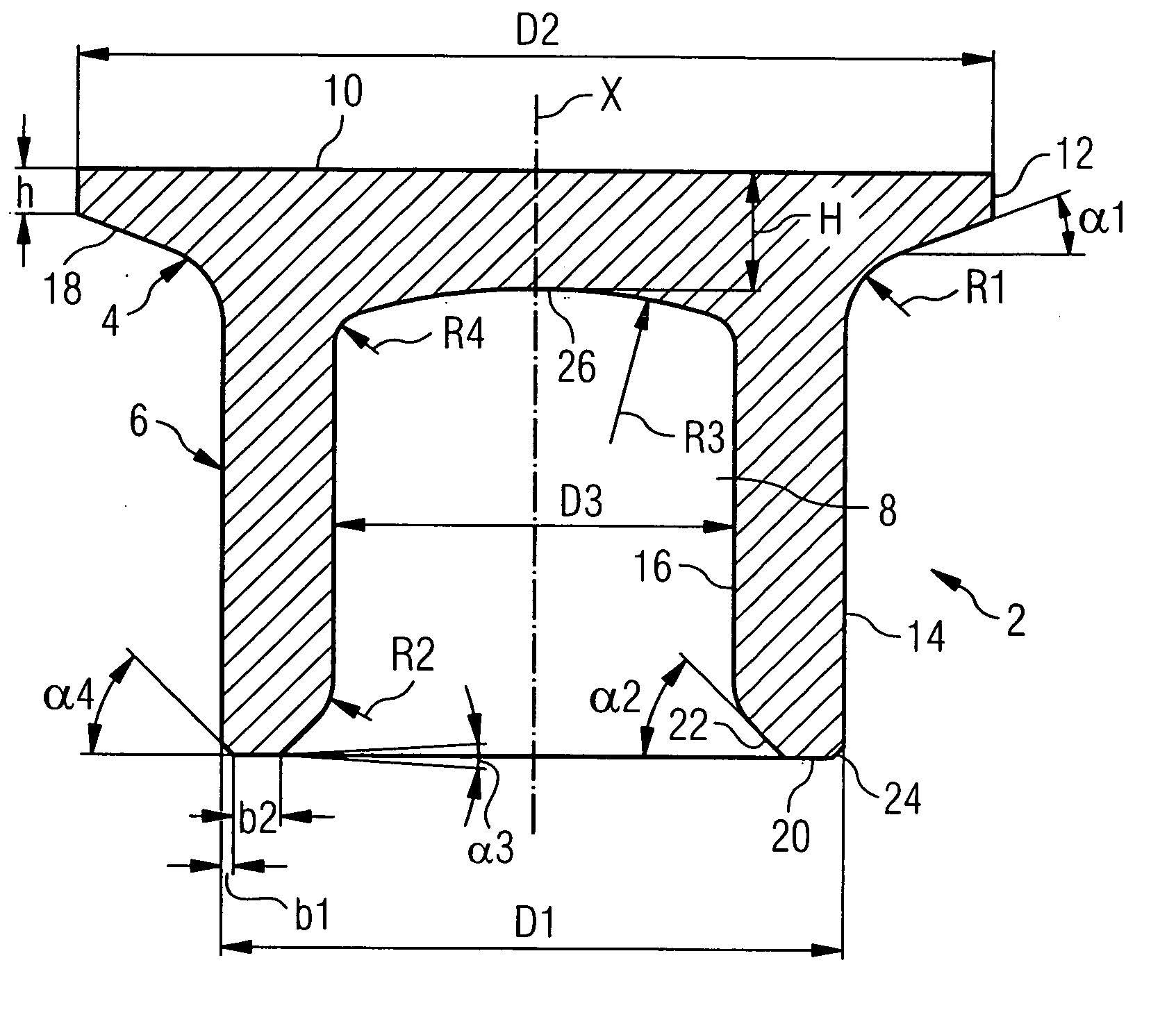
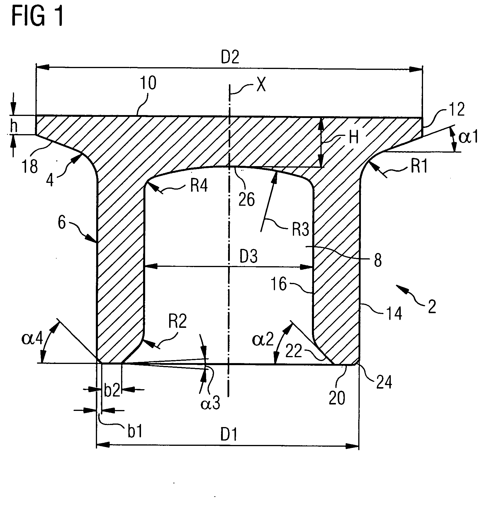
[0028] With the help of FIG. 1 a concrete embodiment of a semihollow self-piercing rivet designed according to the invention is described.

[0029] The self-piercing rivet 2 is designed rotationally symmetrical with reference to a central axis X and consists of a rivet head 4 and a rivet shank 6 with a central hole 8, which is designed as a blind hole.

[0030] The rivet head 4 has a (preferably plane) top side 10 and a (preferably cylindrical) head exterior 12. The head exterior 12 has a diameter D2 and an axial height h.

[0031] The rivet shank 6 has a cylindrical shank exterior 14 and a cylindrical shank interior 16, which bounds the hole 8. The cylindrical shank exterior 14 has a diameter D1, and the cylindrical shank interior has a diameter D3. Reference is made of the fact that the shank exterior 14, for specified application cases, can be designed slightly diverging at least in certain places in order to minimize the gap formation between the joined metal sheet sheets.

[0032] The ...


PUM


Abstract

A self-piercing rivet of a special rivet geometry is described, which in particular is suitable for joining high strength steel sheets, but can also be used for other metal sheets. The self-piercing rivet is in particular characterized by a special underhead geometry as well as a special geometry of the rivet foot (cutting region). Thus the self-piercing rivet has an underhead chamfer which with a radial plane of the self-piercing rivet encloses an angle of 20°+5°/−5° and merges tangentially into the cylindrical outer surface of the rivet shank via a radius. In the region of the rivet foot the self-piercing rivet has a plane shank face, which extends essentially at a right angle to the rivet axis and which merges “smoothly” into the cylindrical inner surface via a shank inner surface and a radius. In comparison to conventional self-piercing rivets the special rivet geometry enables lower joining forces and tensile forces in the joining operation, an optimized load bearing performance and an optimum joint quality of the self-piercing rivet joint as well as minimum gap formation between the rivet and the metal sheet.

Description

BACKGROUND OF THE INVENTION [0001] The present invention relates to a self-piercing rivet in the form of a semihollow self-piercing rivet or full hollow self-piercing rivet for producing a self-piercing rivet joint between two or more metal sheets. [0002] Self-piercing riveting as a joining method has gained increasing importance in the recent past. One important parameter for the joining operation as well as the joining quality of the self-piercing rivet joint is the geometry of the self-piercing rivet. In the state of the art numerous different geometries of the self-piercing rivet are known, see e.g. EP 0 720 695, EP 1 064 466, EP 1 229 254, EP 1 387 093, DE 44 31 769, DE 203 19 610 U1, DE 200 01 103 U1, US 2004 / 0068854 A1, JP 2001159409A, JP 09317730A et alia. [0003] The self-piercing rivet according to the above named EP 0 720 695, which is normally described as a C rivet, is used on a large scale in the motor vehicle industry, but also in other technical fields. This is a semi...

Claims


Application Information

Patent Timeline
Patent Type & Authority Applications(United States)
IPC IPC(8): F16B39/00F16B19/08
CPCF16B19/086
Inventor PHILIPSKOTTER, ANDREECKSTEIN, JOHANNESRUTHER, MICHAELWALTZ, HERBERTPOREPP, ROLAND
Owner BOLLHOFF VERBINDUNGSTECHNIK GMBH
Why Eureka
Try Eureka