Electric heating structure

a technology of electric heating and heating structure, applied in the field of electric heating structure, can solve the problems of poor mechanical strength of shock resistance, poor other problems of non-metal substrates, and achieve the effects of high electric heating conversion efficiency, reduced heat conducting path, and high efficiency

Inactive Publication Date: 2007-05-17
SYNTRAN
View PDF5 Cites 11 Cited by
  • Summary
  • Abstract
  • Description
  • Claims
  • Application Information

AI Technical Summary

Benefits of technology

[0009] In view of the shortcomings of a prior art structure, the primary objective of the present invention is to provide a highly efficient electric heating structure that is substantially a device...

Problems solved by technology

However, most of those convention electric heating products have poor electric heating conversion efficiency, which is the cause of energy loss during the converting of electric power into thermal power that is further being affected by the impedance of the material used as well as the non-Joule thermal energy conversion.
However, using non-metal substrates may have other issues.
In addition to a poor thermal conduction, the mechanical strength of shock resistance is also poor.
Even though the enamel steel plate has a higher thermal con...

Method used


Image

  • Electric heating structure
  • Electric heating structure
  • Electric heating structure

Examples


Embodiment Construction

[0036] For your esteemed members of reviewing committee to further understand and recognize the fulfilled functions and structural characteristics of the invention, several preferable embodiments cooperating with detailed description are presented as the follows.

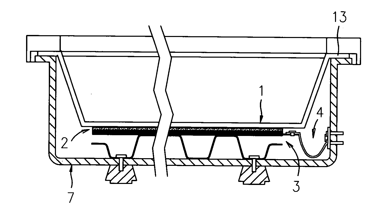
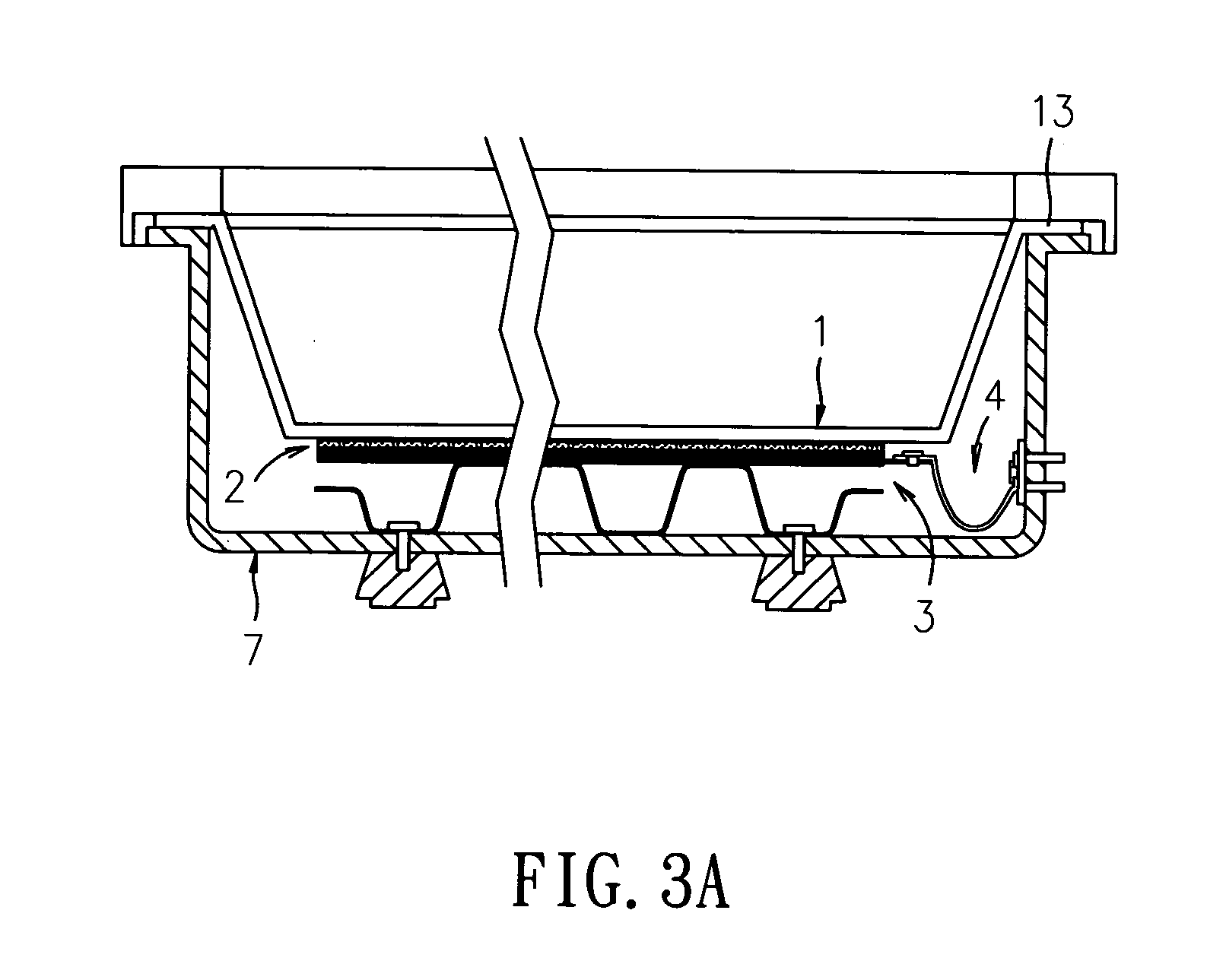
[0037] Referring to FIG. 3A for the cross-sectional view of a structure according to a preferred embodiment of the present invention and FIG. 3B for the enlarged view of the structure. In FIG. 3A and FIG. 3B, an electric heating structure of the invention is primarily comprised of a heat conducting plate 1, a heating plate 2, an electrode fixing structure 3, and a wire connecting structure 4, whereas the heat conducting plate 1, heating plate 2, electrode fixing structure 3, and wire connecting structure 4 are all arranged in a casing 7.

[0038] The heat conducting plate 1 is provided for conducting thermal energy and could be made of a heat conducting metal material such as stainless steel. As seen in FIG. 3A, a lateral sid...


PUM


Abstract

An electric heating structure is disclosed, which comprises: a heat conducting plate for conducting thermal energy; a heating plate, disposed at the bottom of the heat conducting plate; a metal electrode, for conducting electricity; and an electric conducting element. The heating plate is further comprised of a porous insulating layer and an electric heating film made of an oxide of electric conducting ability. By enabling the metal electrode to couple to the electric heating film, and an end of the electric conducting element to couple to the metal electrode while the other end thereof is coupled to a power connecting terminal, an electrical conduction is enabled between the metal electrode, the electric conducting element, and the power connecting terminal. Hence, after electricity of the power connecting terminal is conducted from the electric conducting element to the heating plate, the electric energy is converted by the heating plate into thermal energy to be transmitted to the heat conducting plate for heating the same.

Description

FIELD OF THE INVENTION [0001] The present invention relates to an electric heating structure, and more particularly, to a highly efficient electric heating structure that is substantially a device with reduced heat conducting path realized by the cooperation of an oxide conducting film with high electric heating conversion efficiency, a metallic heat conducting plate, and a porous insulating layer. BACKGROUND OF THE INVENTION [0002] The technical measures taken for converting electric energy into thermal energy have been used extensively in various different electric heating products. In general, a prior art uses a nickel-chromium wire to produce a Joule Effect for converting electric energy into thermal energy. However, most of those convention electric heating products have poor electric heating conversion efficiency, which is the cause of energy loss during the converting of electric power into thermal power that is further being affected by the impedance of the material used as ...

Claims


Application Information

Patent Timeline
IPC IPC(8): H05B3/16
CPCA47J36/2466
Inventor CHENG, SYH-YUHYANG, YU-TSAICHEN, CHING-FENG
Owner SYNTRAN
Why Eureka
Try Eureka