Ultrasonic diagnostic apparatus and ultrasonic probe

a diagnostic apparatus and ultrasonic technology, applied in the direction of mechanical vibration separation, instruments, piezoelectric/electrostrictive/magnetostrictive devices, etc., can solve the problems of loss of ultrasonic waves, discontinuous rate of change of acoustic impedance, and discontinuous face of slope matching layers of prior art, so as to improve the efficiency of ultrasonic wave propagation

Inactive Publication Date: 2007-05-17
TOSHIBA MEDICAL SYST CORP
View PDF6 Cites 9 Cited by
  • Summary
  • Abstract
  • Description
  • Claims
  • Application Information

AI Technical Summary

Benefits of technology

[0010] According to one aspect of the present invention, there is provided an ultrasonic apparatus diagnostic and an ultrasonic probe in which efficiency of propagation of ultrasonic waves is improved.

Problems solved by technology

However, the slope matching layers of the prior art also have discontinuous faces.
However, the rate of change of acoustic impedance is discontinuous at a boundary interface between an acoustic matching layer and an acoustic lens and a boundary face between an acoustic matching layer and a piezoelectric vibrator.
In consequence, this discontinuous interface causes generation of reflection from the boundary, which leads to a loss of ultrasonic wave and deters image diagnostics.

Method used


Image

  • Ultrasonic diagnostic apparatus and ultrasonic probe
  • Ultrasonic diagnostic apparatus and ultrasonic probe
  • Ultrasonic diagnostic apparatus and ultrasonic probe

Examples


first exemplary embodiment

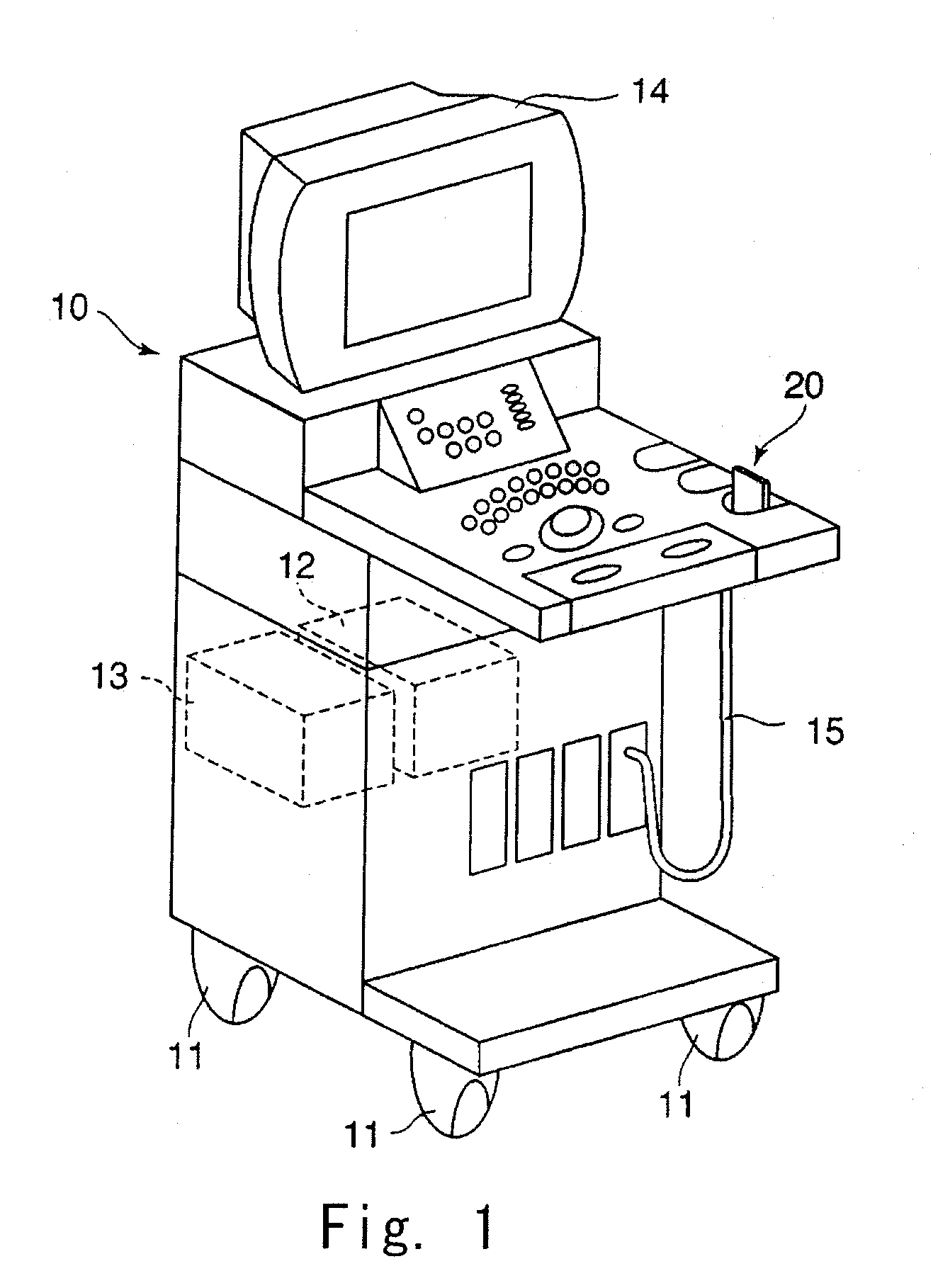
[0032] As shown in FIG. 1, an ultrasonic diagnostic apparatus of a first exemplary embodiment includes an apparatus body 10 and an ultrasonic probe 20. A wheel 11 is fastened at the apparatus body 10 so that an operator can move it to bedside. A transmitting and receiving circuit 12 and an image generation unit 13 are set within the apparatus body 10. The transmitting and receiving circuit 12 applies driving signals to the ultrasonic probe 20 and generates a receiving signal based on echo signals obtained by the ultrasonic probe 20. An image generation unit 13 generates an ultrasonic image of the subject on the basis of the receiving signals generated by the transmitting and receiving circuit 12. On the apparatus body, there is provided a monitor 14 which displays an ultrasonic image generated by the image generation unit 13. The apparatus body 10 and the ultrasonic probe 20 are connected by a cable 15. Data is exchanged between the apparatus body 10 and the ultrasonic probe 20 over...

second exemplary embodiment

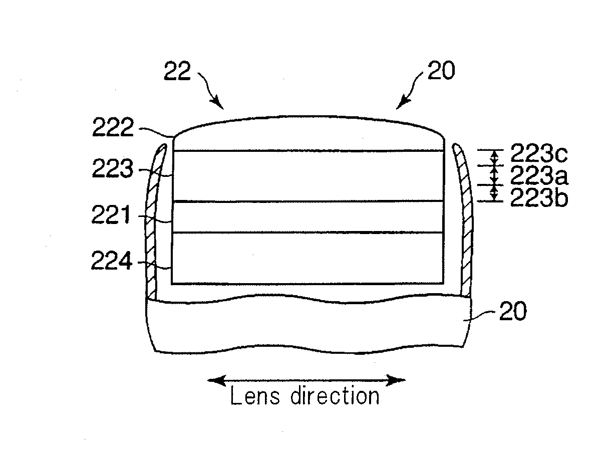
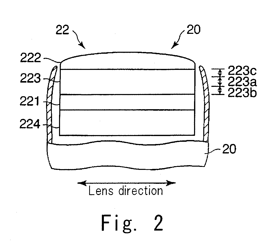
[0076] As shown in FIG. 12, the transducer 22 of this second exemplary embodiment includes a sub acoustic matching layer 223′ between the piezoelectric vibrator 221 and the acoustic matching layer 223. In other words, the transducer 22 of this exemplary embodiment includes two matching layers.

[0077] The acoustic impedance of the sub acoustic matching layer 223′ is about 12 Mraly. The acoustic impedance of the end contacting the sub acoustic matching layer 223′ of the acoustic matching layer 223 is 12 Mraly, which is the same as that of the sub acoustic matching layer 223′.

[0078] In this component, at a border portion between the acoustic matching layer 223 and the sub acoustic matching layer 223′ and a border portion between the acoustic matching layer 223 and the acoustic lens 222, acoustic impedance hardly changes. Therefore, because reflection of ultrasonic waves decreases, efficiency of propagation of ultrasonic waves is improved.

[0079] Furthermore, the acoustic matching laye...

third exemplary embodiment

[0080] As shown by FIG. 13, in a manufacturing process of the transducer 22 of this exemplary embodiment, at first, as shown by FIG. 13(a), liquid of first plastic 223A(1) is coated on a front surface of the piezoelectric vibrator 221. The acoustic impedance of the first plastic 223A(1) is the same as that of the first matching layer 221. The acoustic impedance of first plastic 223A(1) is dependent on addition of filler, for example, made from silica powder or tungsten powder. After hardening of the first plastic 223A(1), as shown in FIG. 13(b), the first plastic 223A(1) is grinded so as to have predetermined thickness. As a result, the first matching layer 223(1) is formed on the front surface of the piezoelectric vibrator 221. The thickness of the first matching layer 223(1) is less than a fortieth part of wavelength of ultrasonic waves, as in the first exemplary embodiment.

[0081] In a similar manner, the second matching layer 223(2), the third matching layer 223(3) . . . and the...


PUM


Abstract

An ultrasonic probe including a piezoelectric vibrator configured to transmit and receive ultrasonic waves, an acoustic lens configured to focus the ultrasonic waves and an acoustic matching layer arranged between the piezoelectric vibrator and the acoustic lens and configured to modify acoustic impedance from the piezoelectric vibrator to the acoustic lens. The acoustic matching layer includes a first region arranged at center areas along a direction of transmitting and receiving of the ultrasonic waves, a second region arranged between the first region and the piezoelectric vibrator and having a rate of change of acoustic impedance which is less than rate of change of acoustic impedance of the first region and a third region arranged between the first region and the acoustic lens, and having a rate of change of acoustic impedance which is less than a rate of change of acoustic impedance of the first region.

Description

CROSS-REFERENCE TO RELATED APPLICATIONS [0001] This application is based upon and claims the benefit of priority from the prior Japanese Patent Application No. 2005-320995, filed on Nov. 4, 2005, the entire contents of which are incorporated herein by reference. BACKGROUND OF THE INVENTION [0002] An ultrasonic diagnostic apparatus is a diagnostic imaging apparatus that provides images inside of a subject on the basis of reflected ultrasonic waves by transmitting ultrasonic waves from an ultrasonic probe to a subject, and receiving reflected waves from regions of discordant acoustic impedance by the ultrasonic probe. [0003] In a known ultrasound imaging device, a plurality of acoustic matching layers having thicknesses of less than a quarter of ultrasonic wave length are layered between a piezoelectric vibrator and an acoustic lens. This technique is intended to match the acoustic impedance of a piezoelectric vibrator to the acoustic impedance of the acoustic lens. Many matching laye...

Claims


Application Information

Patent Timeline
Patent Type & Authority Applications(United States)
IPC IPC(8): H01L41/08
CPCB06B1/0622G10K11/02
Inventor SHIBAMOTO, KOICHIAOKI, MINORUMAKITA, YASUHISATAKEUCHI, TAKAKSHISHIKATA, HIROYUKI
Owner TOSHIBA MEDICAL SYST CORP
Why Eureka
Try Eureka