[0004] In view of the above problem, the present invention has been accomplished to provide a
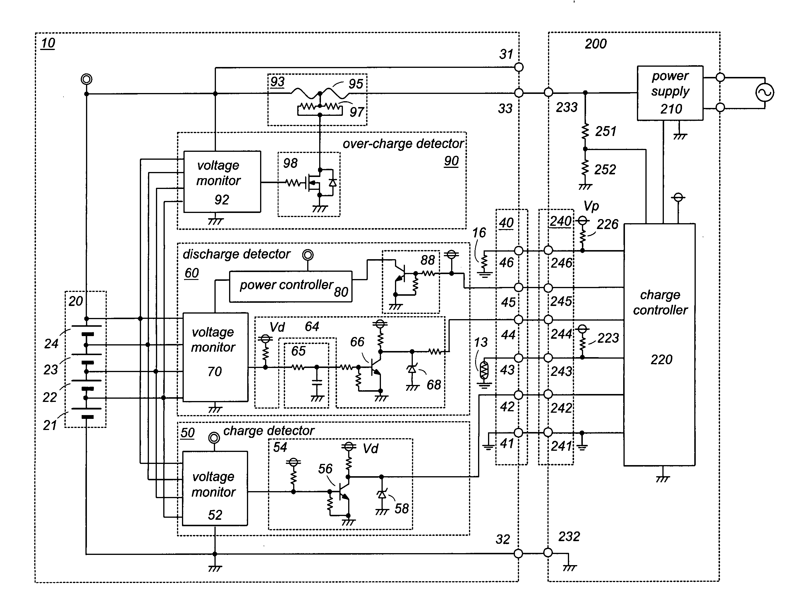
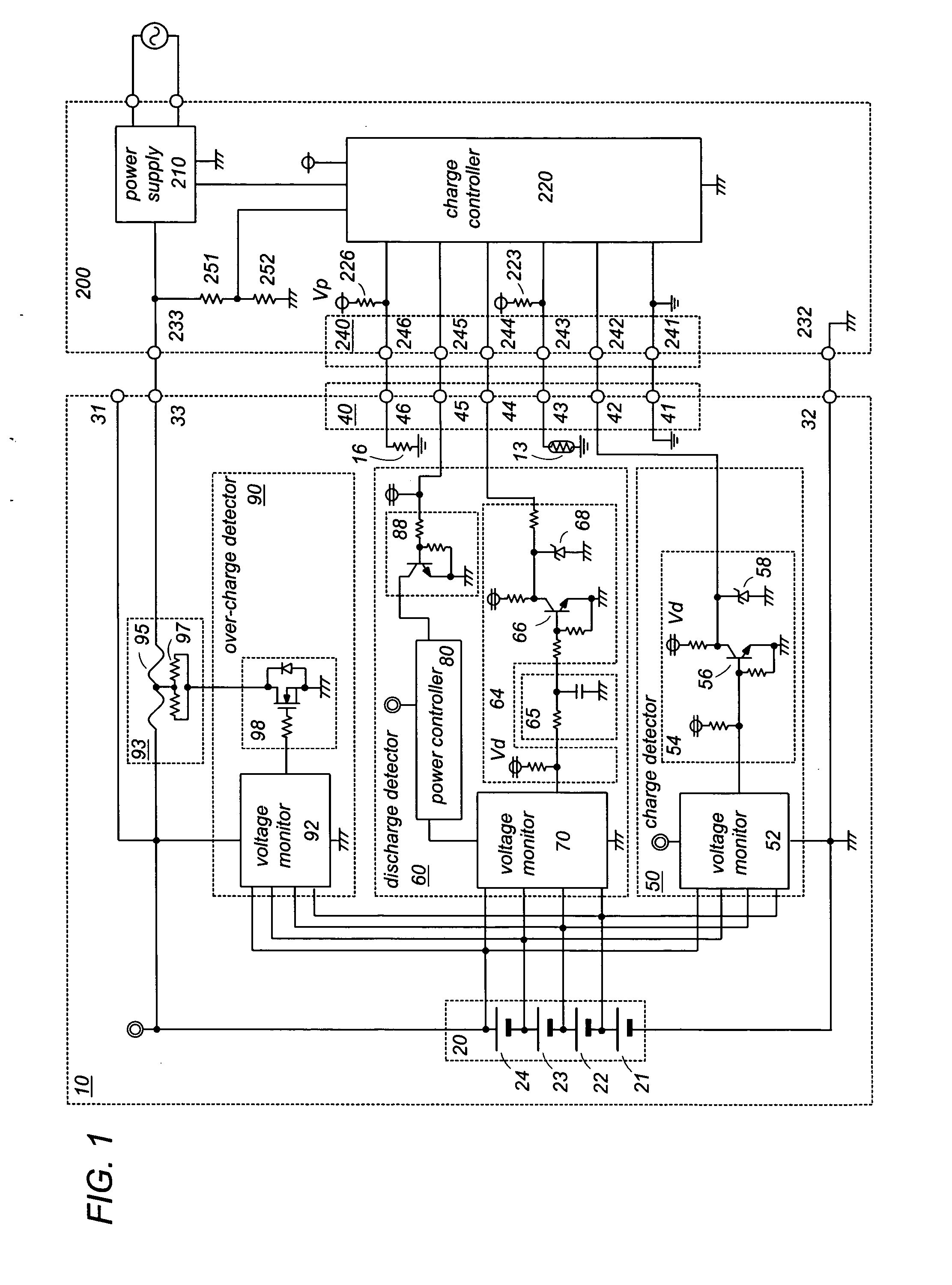
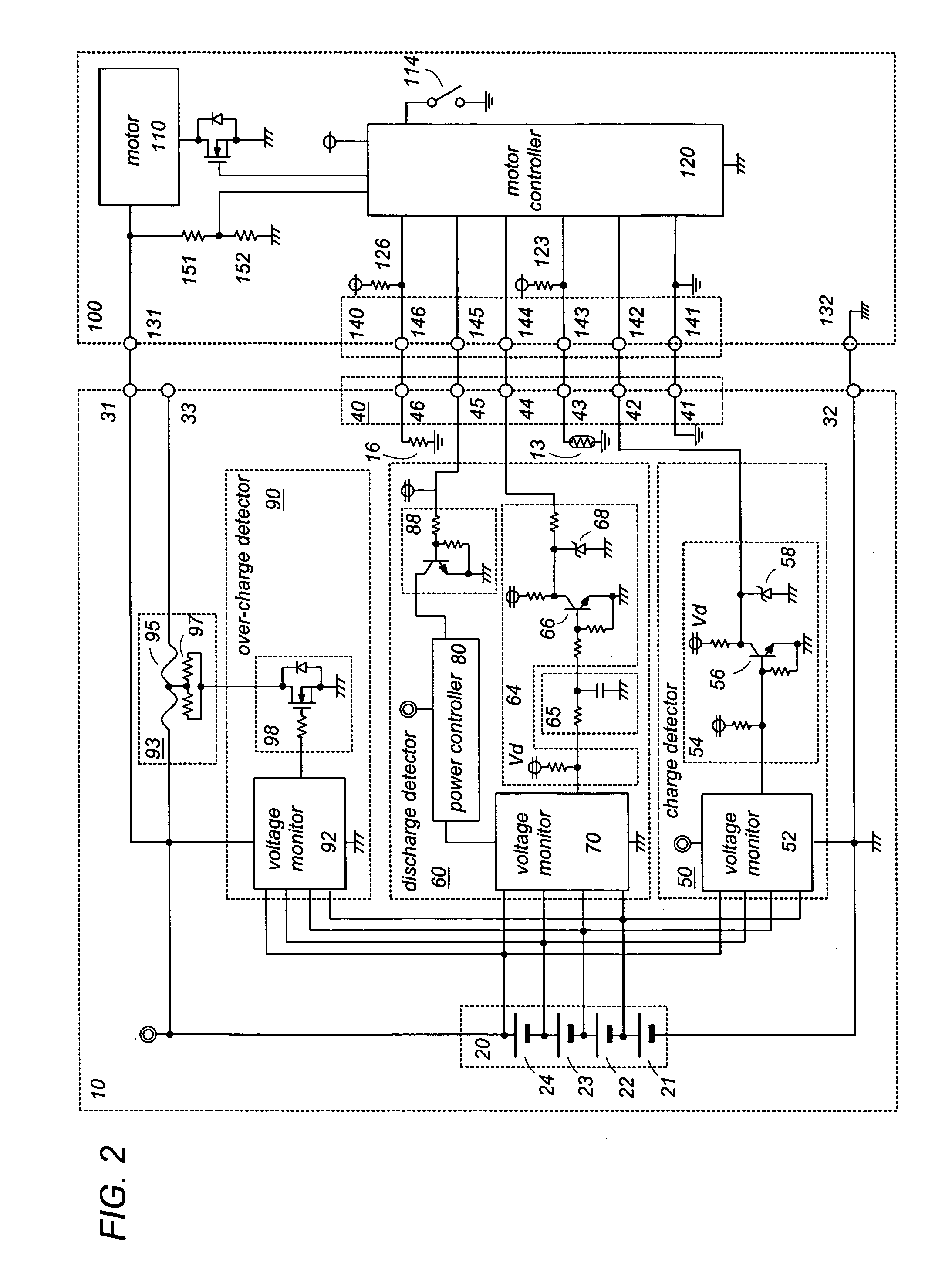
rechargeable battery pack for a power tool which has a self-contained over-charge protection capable of protecting the battery from being over-charged even if an associated charger fails to limit a charge current. The battery pack in accordance with the present invention includes a battery stack composed of a plurality of series connected secondary cells, a pair of
power output terminals connected across the battery stack to supply a
voltage of the battery stack for operating the power tool, and a
signal connector configured to include a
charge control terminal, a
discharge control terminal, and a
signal ground terminal connected to a circuit ground. The battery pack includes a charge
detector which is configured to monitor a
cell voltage across each one of the secondary cells and to provide a high charge-
control signal when all of the cell voltages are lower than a first threshold (VTH1) and a low charge-
control signal when any one of the
cell voltage becomes higher than the first threshold (VTH1). The high charge-
control signal and the low charge-control
signal are fed through the
charge control terminal to a charger for regulating a charge current of charging the secondary cells. The battery pack also includes a
discharge detector which is configured to monitor the
cell voltage across each of the secondary cells and to provide a
discharge stop signal when any one of the cell voltages becomes lower than a second threshold (VTH2) which is lower than the first threshold (VTH1). The discharge
stop signal is fed through the discharge control terminal to the power tool for deenergizing the power tool. The battery pack is also provided with a charge terminal which is separated from one of the
power output terminals and is connected to the battery stack for flowing the charge current from the charger to the secondary cells not through the one of the
power output terminals. An
interrupter is inserted in a charge current path between the charge terminal and the battery stack. The present invention is characterized by an over-charge detector which is included in the battery pack to monitor the
cell voltage across each of the secondary cells and to actuate the interrupter to open the charge current path when any one of the cell voltages becomes higher than a third threshold (VTH3) which is higher than the first threshold (VTH1). Thus, even if the charger fails to limit the charge current, the battery pack can itself protect the secondary cells from being over-charged.
[0006] The discharge detector is preferred to include a voltage monitor and a
power controller. The voltage monitor comprises a plurality of comparators and a plurality of
constant voltage elements each providing a
constant voltage that defines the second threshold (VTH2). Each of the comparators is configured to compare each of the monitored cell voltages with the second threshold to give a comparison result such that the discharge detector provides the discharge
stop signal to the discharge control terminal based upon the comparison results. The
power controller is configured to connect the battery stack to the voltage monitor when the battery pack is connected to the power tool. Thus, the voltage monitor is made active in response to the battery pack being connected to the power tool, and can be therefore free from consuming a current from the battery stack in the absence of the power tool, i.e., the
discharge current being supplied to the power tool. With this result, the battery pack can minimize
power consumption within the discharge detector when the battery pack is being disconnected from the power tool. The
power controller is configured to have a plurality of different current supply paths which supply a current from a common potential of the battery stack respectively to different potentials of the battery stack through each one of the
constant voltage sources. Each of the current supply paths includes a switch which is configured to close only in response to a detection signal issued when the battery pack is connected to the power tool. Accordingly, no leak current flows across each of the secondary cells while the battery pack is left disconnected from the power tool, whereby it is possible to keep the voltage monitor disconnected entirely from the battery stack, assuring to consume no substantial power of the battery pack when the battery pack is left disconnected from the power tool.
[0008] The power output terminals are composed of a positive output terminal and a ground terminal which is preferably isolated electrically from the circuit ground such that the charge current or
discharge current can be well prevented from flowing even if the
electrical connection between the battery pack and the charger or the power tool should fail.
[0009] The battery pack of the present invention may further include a
temperature sensing element and an ID
resistor having a resistance indicative of a kind of the battery stack. The
temperature sensing element is connected across a temperature output terminal of the signal connector and the signal ground terminal to provide a temperature signal indicative of a temperature of the battery stack to the temperature output terminal. The ID
resistor is connected across an ID output terminal of the signal connector and the signal ground terminal to provide the resistance to the ID output terminal. With the inclusion of these elements, it is possible to give an
optimum control of charging the battery stack on the side of the charger and of operating the power tool in well consideration of the temperature and the kind of the battery stack.

