Stage apparatus, exposure apparatus, and exposure method

a technology of stage apparatus and exposure apparatus, applied in the direction of photomechanical apparatus, instruments, printing, etc., can solve the problems of mechanical parts rusting, degrading the projected pattern image, and insufficient margin, so as to prevent the infiltration of liquid, prevent the infiltration, and prevent the infiltration

Inactive Publication Date: 2007-05-17
NIKON CORP
View PDF99 Cites 69 Cited by
  • Summary
  • Abstract
  • Description
  • Claims
  • Application Information

AI Technical Summary

Benefits of technology

[0016] Accordingly, because the lyophilic parts of the stage apparatus of the present invention have an affinity for the liquid, it is possible to guide the liquid that infiltrates the vicinity of the holder in a direction away from the substrate holding surface, and then recover the liquid. Consequently, it is possible to prevent the infiltration of the liquid between the substrate holding surface and the rear surface of the substrate, and thereby to expose the edge area of the substrate in a state wherein the immersion area is satisfactorily formed.
[0017] In addition, an exposure apparatus of the present invention comprises a stage apparatus as described in the claims. Furthermore, an exposure method of the present invention is to transfer a mask pattern through a projection optical system onto a substrate on a holder while filling the liquid between the projection optical system and the substrate and performing an exposure while preventing the infiltration of the liquid into the space between the substrate holding surface and the rear surface of the substrate.
[0018] With the exposure apparatus and the exposure method of the present invention, it is possible to prevent the infiltration of the liquid into the space between the substrate holding surface and the rear surface of the substrate, even when filling the liquid between the projection optical system and the substrate and exposing the edge area of the substrate. Accordingly, it is possible to perform an exposure while satisfactorily holding the substrate.
[0019] With the present invention, the liquid can be prevented from traveling around to the space between the substrate and the holder, even when exposing the edge area of the substrate, and it is thereby possible to perform an immersion exposure while satisfactorily holding the liquid below the projection optical system.

Problems solved by technology

At this time, if the depth of focus δ becomes excessively narrow, then it will become difficult to align the front surface of the substrate with the image plane of the projection optical system, and there will be a risk of insufficient margin during the exposure operation.
Nevertheless, the related art discussed above has the following types of problems.
Nevertheless, if an attempt is made to set the projection area 100 of the projection optical system to a peripheral area (edge area) E of a substrate P and then expose the edge area E of the substrate P, as depicted by the schematic diagram of FIG. 10, there is a problem in that the liquid flows out to the outer side of the substrate P, and therefore the immersion area does not form satisfactorily, which degrades the projected pattern image.
In addition, the liquid that flows out can also cause problems such as rusting of mechanical parts and the like around the substrate stage that supports the substrate P, as well as electrical leakage of the stage drive system and the like.
Furthermore, if the liquid that flows out to the outer side of the substrate P travels around to the rear surface of the substrate P and infiltrates the space between the substrate P and the substrate stage (substrate holder), then it will also cause a problem wherein the substrate stage cannot satisfactorily hold the substrate P. In addition, if the liquid infiltrates the step or the gap between the substrate P and the substrate stage, then in this case as well there is a possibility that the liquid will cause rust or electric leakage.

Method used


Image

  • Stage apparatus, exposure apparatus, and exposure method
  • Stage apparatus, exposure apparatus, and exposure method
  • Stage apparatus, exposure apparatus, and exposure method

Examples


first embodiment

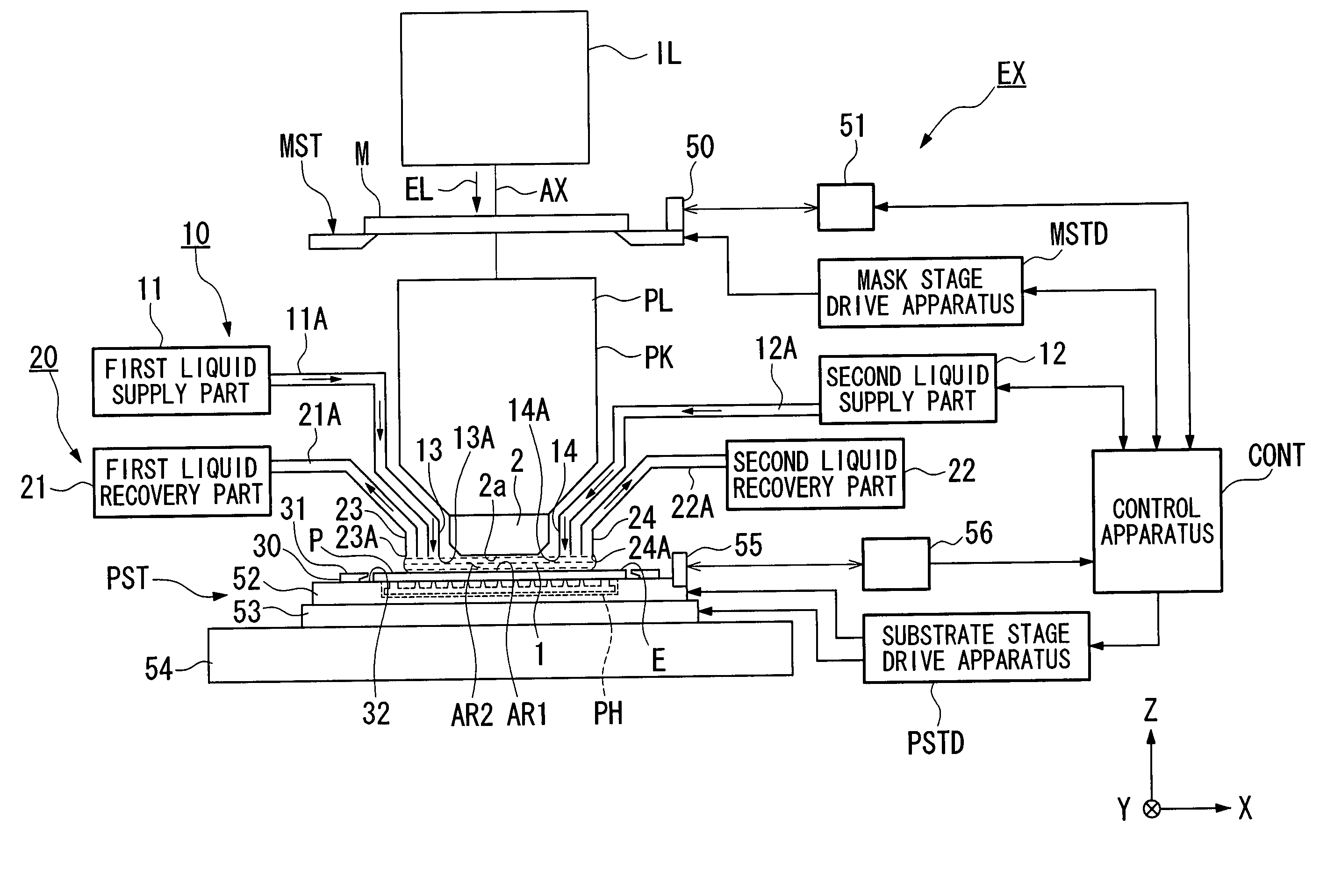
[0031] In FIG. 1, an exposure apparatus EX comprises: a mask stage MST that supports a mask M; a substrate stage PST that supports a substrate P; an illumination optical system IL that illuminates the mask M, which is supported by the mask stage MST, with an exposure light EL; a projection optical system PL that projects and exposes a pattern image of the mask M illuminated by the exposure light EL onto the substrate P supported by the substrate stage PST, which functions as the stage apparatus; and a control apparatus CONT that provides overall control of the operation of the entire exposure apparatus EX.

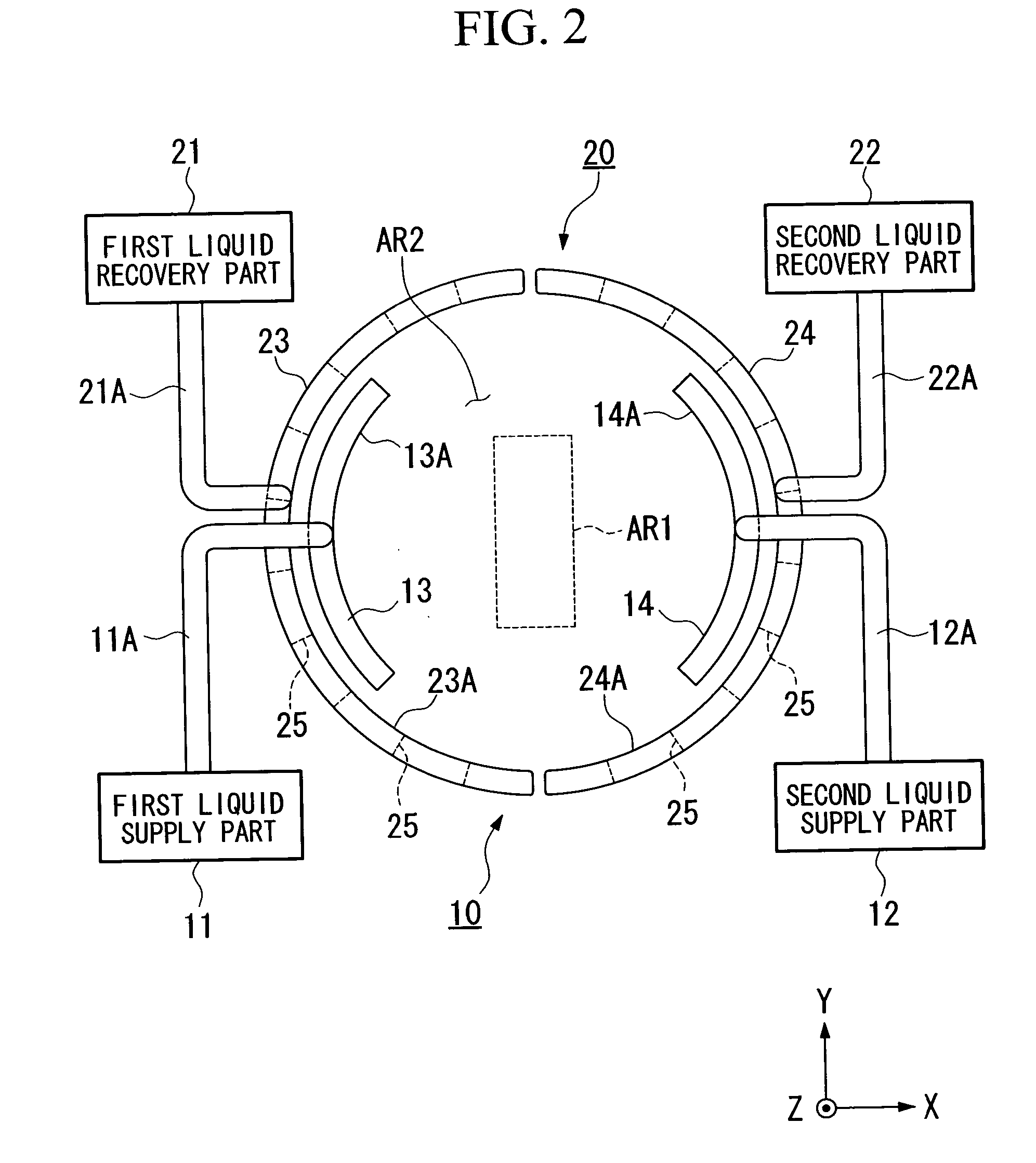
[0032] The exposure apparatus EX of the present embodiment is a liquid immersion type exposure apparatus that applies the liquid immersion method to substantially shorten the exposure wavelength, improve the resolution, as well as substantially increase the depth of focus, and comprises a liquid supply mechanism 10 that supplies a liquid 1 between the projection optical system PL ...

second embodiment

[0070]FIG. 5 and FIG. 6 depict the second embodiment of the stage apparatus of the present invention.

[0071] With the first embodiment, the liquid 1 travels to the inclined surface of the plate part 30 due to its own weight, and is guided in a direction away from the substrate P; however, the second embodiment adopts a constitution wherein the liquid 1 is suctioned using the capillary phenomenon.

[0072] The following explanation is made referencing FIG. 5 and FIG. 6.

[0073] Furthermore, constituent elements in FIG. 5 and FIG. 6 that are identical to those in the first embodiment, which is depicted in FIG. 4 and the like, are assigned the identical symbols, and the explanations thereof are omitted.

[0074] As depicted in FIG. 5, the plate part 30 in the present embodiment comprises a rear surface 7 extending in the horizontal direction (substantially parallel to the substrate holding surface 33A) from the lower end part 4, which surves as a base end, of the inner circumferential surfa...

third embodiment

[0080]FIG. 7 depicts the third embodiment of the stage apparatus of the present invention.

[0081] With the present embodiment, the liquid 1 is suctioned and recovered using the lyophilic parts and the suction pressure differential with respect to the plate part 30 and the substrate P.

[0082] The following explanation is made referencing FIG. 7. Furthermore, in FIG. 7, constituent elements that are identical to those in the first embodiment, which is depicted in FIG. 4 and the like, are assigned the identical symbols, and the explanations thereof are omitted.

[0083] As depicted in FIG. 7, the plate part 30 in the present embodiment is formed in a ring plate shape, and is mounted and fixed onto the substrate table 52. A groove 9, which is upwardly open, is formed in the substrate table 52 around its entire circumference at a position wherein it is covered by the plate part 30. Furthermore, the passageway 62 of the suction apparatus 60 is provided to the substrate table 52, and connect...


PUM

PropertyMeasurementUnit
wavelengthaaaaaaaaaa

Abstract

A stage apparatus PST is provided with a holder PH, which has a substrate holding surface 33A that holds a substrate P; a stage 52, which supports and moves the holder PH; and a recovery apparatus 60, which is disposed in the vicinity of the holder PH and has lyophilic parts 3, 5 of which at least a part of each is lyophilic, that uses the lyophilic parts 3, 5 to recover a liquid 1. As a result, the infiltration of liquid into the space between the substrate and the holder is prevented, even if performing an exposure treatment by filling the space between a projection optical system and the substrate with the liquid.

Description

BACKGROUND OF THE INVENTION [0001] 1. Field of the Invention [0002] The present invention relates to a stage apparatus having a holder that holds a substrate as well as a stage that supports and moves the holder, an exposure apparatus comprising the stage apparatus, and an exposure method; more particularly, the present invention relates to a stage apparatus, an exposure apparatus, and an exposure method suited for use when exposing a substrate with an image of a pattern through a projection optical system and a liquid. In addition, the disclosure of the following priority application is hereby incorporated by reference in its entirety: Japanese Patent Application No. 2003-416712, filed on Dec. 15, 2003. [0003] 2. Description of the Related Art [0004] Semiconductor devices and liquid crystal display devices are fabricated by a so-called photolithography technique, wherein a pattern formed on a mask is transferred onto a photosensitive substrate. [0005] An exposure apparatus used in ...

Claims


Application Information

Patent Timeline
Patent Type & Authority Applications(United States)
IPC IPC(8): G03B27/58G03F7/20
CPCG03F7/70341G03F7/2041G03F7/70716H01L21/0274
Inventor NISHII, YASUFUMISHIRAISHI, KENICHIKOHNO, HIROTAKA
Owner NIKON CORP
Why Eureka
Try Eureka