Electric double layer capacitor and aggregation thereof

a double layer capacitor and aggregation technology, applied in the direction of hybrid capacitor terminals, multiple hybrid/edl capacitors, electrolytic capacitors, etc., can solve the problems of solid electrolytic capacitors that do not lend themselves to an increase capacity, and the size of the reduction is remarkable, so as to achieve a large capacitance and small size. , the effect of thinness

Inactive Publication Date: 2007-05-17
ROHM CO LTD
View PDF5 Cites 30 Cited by
  • Summary
  • Abstract
  • Description
  • Claims
  • Application Information

AI Technical Summary

Benefits of technology

[0008] In order to overcome the problems described above, preferred embodiments of the present invention...

Problems solved by technology

Although high in capacitance, the electric double layer capacitor X has a structure sealed entirely by a metal cylinder can and does not re...

Method used


Image

  • Electric double layer capacitor and aggregation thereof
  • Electric double layer capacitor and aggregation thereof
  • Electric double layer capacitor and aggregation thereof

Examples


Embodiment Construction

[0039] Preferred embodiments of the present invention will be described specifically with reference to the drawings as below.

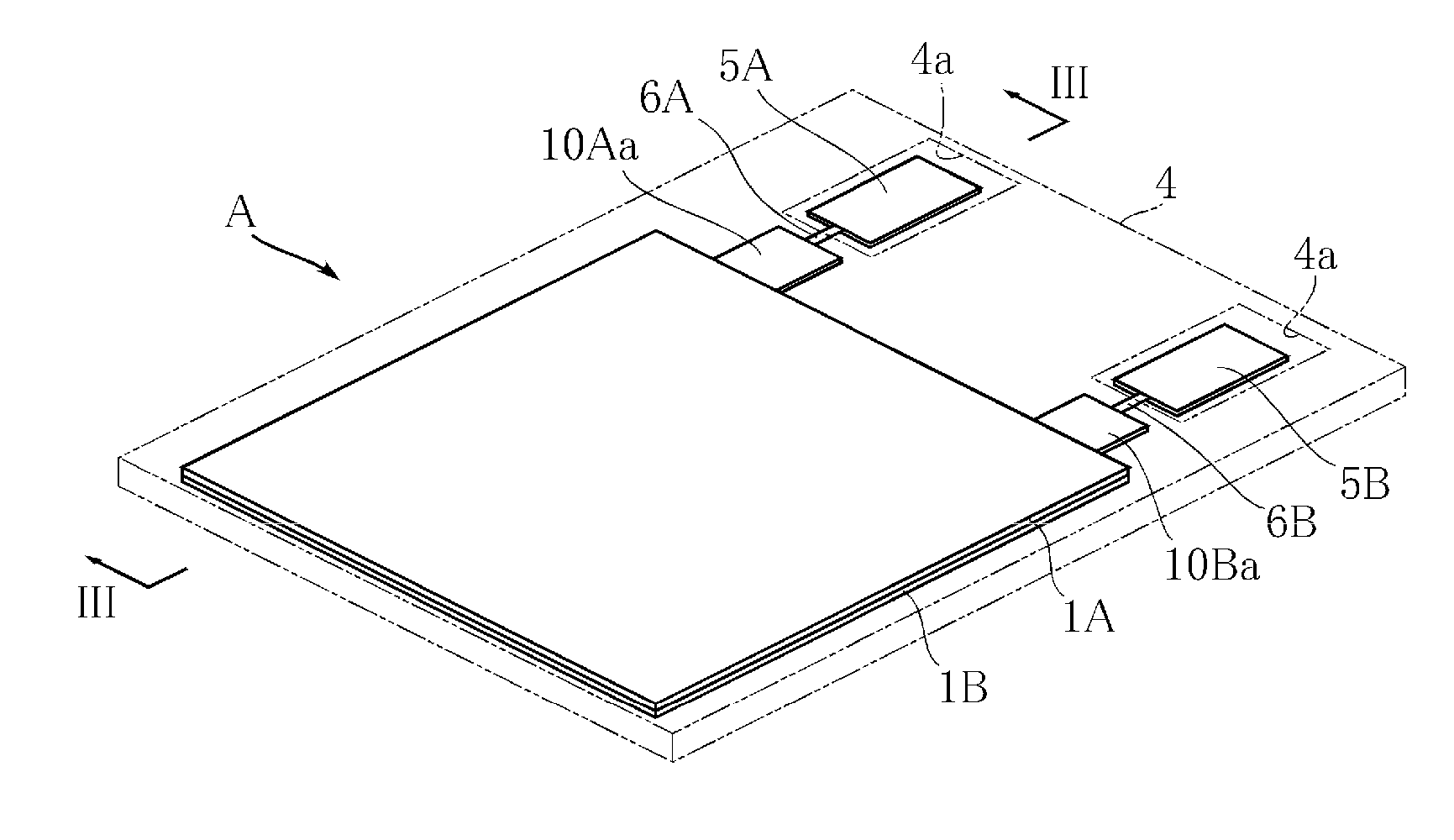
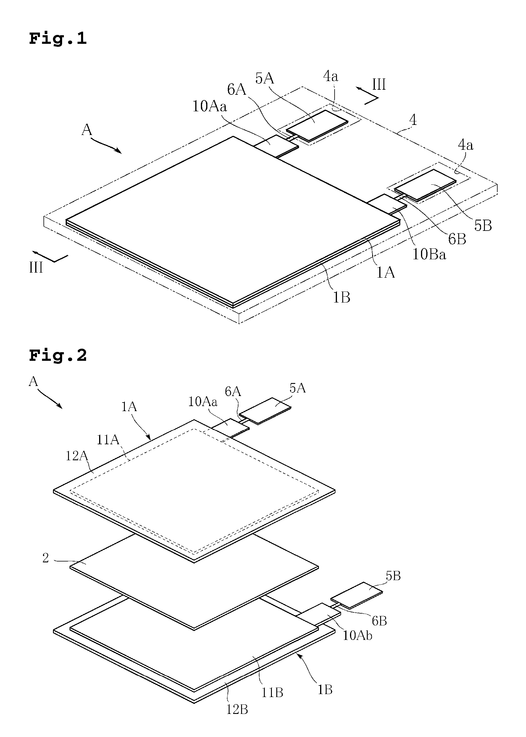
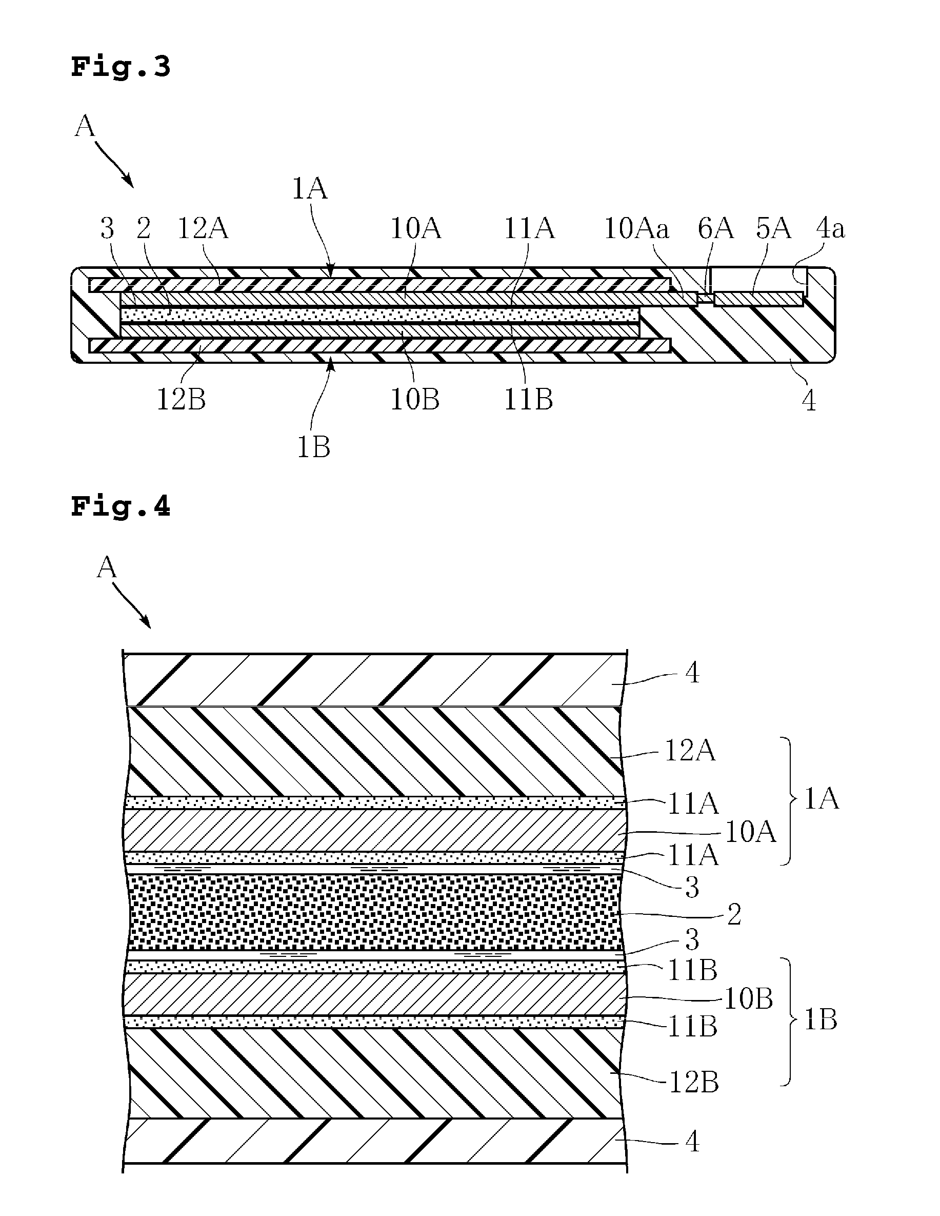
[0040]FIG. 1 to FIG. 5 show one example of an electric double layer capacitor according to a preferred embodiment of the present invention. The electric double layer capacitor A includes a pair of electrodes 1A, 1B, a partition wall 2, an electrolytic solution 3, a resin package 4, a pair of external connecting terminals 5A, 5B, and high-resistance portions 6A, 6B. FIG. 2 is an exploded perspective view of the electric double layer capacitor A with the electrolytic solution 3 and the resin package 4 omitted. FIG. 4 is a partial enlarged view of FIG. 3. FIG. 5 illustrates the electric double layer capacitor A in a bending state.

[0041] The pair of electrodes 1A, 1B are arranged separated from and opposite to each other, as shown in FIG. 3. In using the electric double layer capacitor A, either one of the pair of electrodes 1A, 1B may be an anode and the other ...


PUM


Abstract

An electrolyte capacitor includes an anode, a cathode, and an electrolytic solution provided between the anode and the cathode. The anode may be a niobium porous sintered body with an oxide film formed as a dielectric layer on a surface thereof. The cathode allows an electric double layer at an interface with the electrolytic solution. The electrolyte capacitor has a large capacitance and increased voltage.

Description

BACKGROUND OF THE INVENTION [0001] 1. Field of the Invention [0002] The present invention relates to an electric double layer capacitor and aggregation thereof. [0003] 2. Description of the Related Art [0004] Capacitors are utilized in backup power supplies and auxiliary power supplies for portable electronic equipment including cell phones, rechargeable devices with solar batteries, and even motor power supplies or regenerative energy devices for so-called hybrid cars. In particular, electric double layer capacitors are suited for use in applications where large capacities are required. [0005]FIG. 15 shows one example of a conventional electric double layer capacitor. This electric double layer capacitor X includes an anode 91 and a cathode 92 having distribution electrodes 91a, 92a made from activated carbon, respectively. A partition wall 93 and an electrolytic solution 94 are arranged between the distribution electrodes 91a, 92a. In the electric double layer capacitor X, so-call...

Claims


Application Information

Patent Timeline
IPC IPC(8): H01G9/00H01G11/10H01G11/00H01G11/22H01G11/24H01G11/42H01G11/66H01G11/74H01G11/78H01G11/86
CPCH01G9/058H01G9/155H01G11/10H01G11/12H01G11/26H01G11/32H01G11/84Y02E60/13H01G9/016H01G11/74H01G11/22
Inventor KURIYAMA, CHOJIROYANAGISAWA, HIROYUKI
Owner ROHM CO LTD
Why Eureka
Try Eureka