
Vehicle simulator

a simulator and vehicle technology, applied in the field of vehicle simulators, can solve the problems of difficult swap between the use of a simulator for one purpose, and the difficulty of programming software and firmware, etc., to achieve the effect of avoiding the need for complex mechanical structure or difficulty in programming software and firmwar

Inactive Publication Date: 2007-05-17
LEFTON NORMAN
View PDF3 Cites 16 Cited by
  • Summary
  • Abstract
  • Description
  • Claims
  • Application Information

AI Technical Summary

Benefits of technology

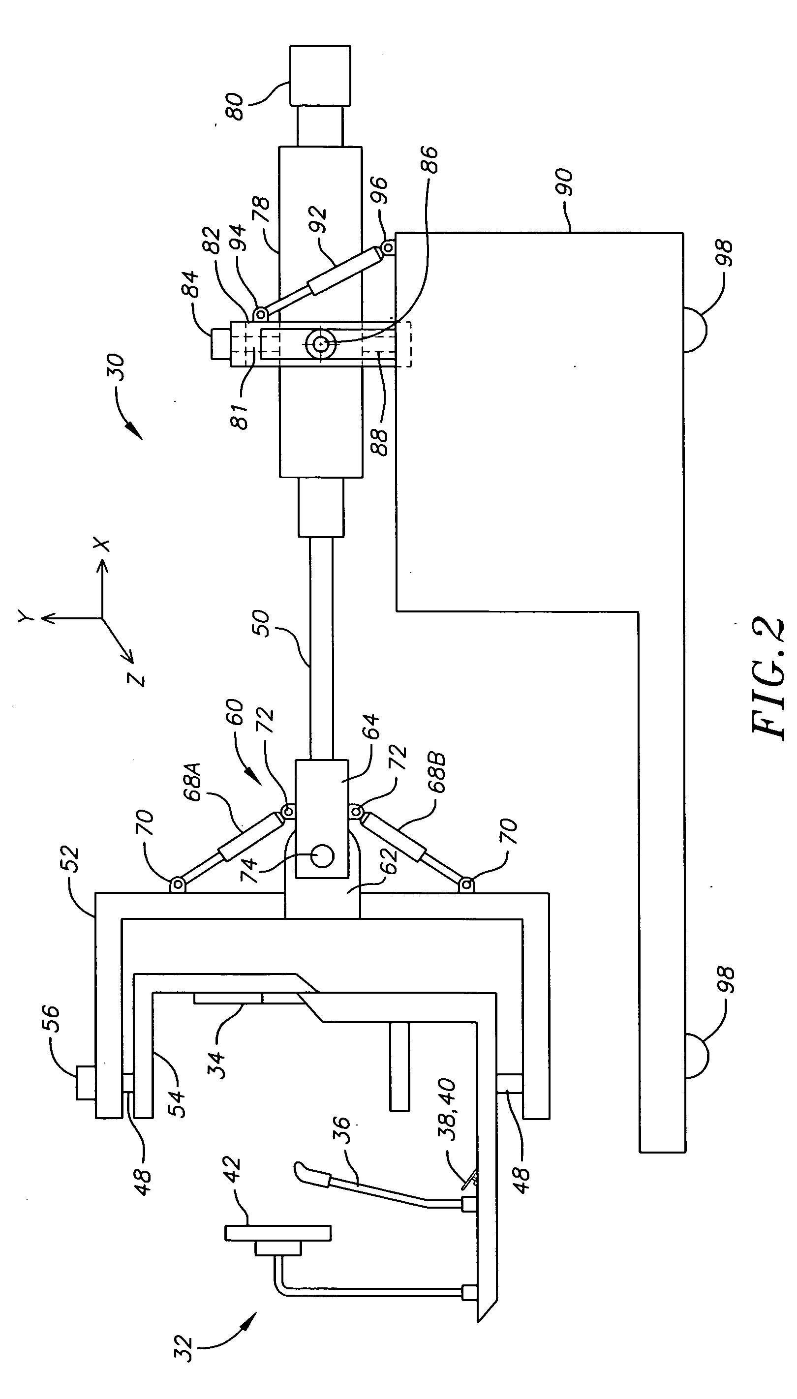
[0007] The vehicle simulator and vehicle operator environment may optionally provide for adaptability to various simulator environments, e.g., helicopters, tanks, fixed wing aircraft, trucks, motorcycles, spacecraft, etc., without requiring complex reprogramming or replacement of the entire operator environment. The vehicle simulator provides for up to six degrees of freedom of motion, which comprise rotational motion of the operator environment around the x, y and z axis, plus translational motion of the vehicle operator environment in lateral x, lateral y, and lateral z directions, to provide for full range of motions including full spins, rolls, and other motions which are not possible with present day vehicle simulators based on a motion base consisting of a plurality of cylinders connected between the base and a floating platform.
[0008] The vehicle simulator of the invention can move in the six degrees of freedom based on a relatively simple design that uses groups of actuating cylinders, motors, or other motion control devices to move the operator environment along the desired axes of rotation and longitudinal motion, and can thus obviate the need for complex mechanical structure or difficult to program software and firmware.

Problems solved by technology

Due to the complicated nature of the various motions required by the cylinders to achieve a desired effect, a considerable degree of programming with tight tolerances is required for effective operation.
Moreover, these types of motion bases are very heavy, and must be mounted to a very secure foundation, such as a six-foot thick reinforced concrete base due to the shaking forces created by the motion base.
Typically, it is difficult to swap between the use of a simulator for one purpose (e.g., helicopter simulator) with another purpose (e.g., tank simulator), since it requires a substantial amount of reprogramming and customization.
Moreover, most simulators operate either in a limited number of degrees of freedom of motion, i.e., translational motion in the x, y and / or z planes, and rotational motion along x, y or z axes, and / or their range of translational motions or rotational motions are limited.

Method used


Image

  • Vehicle simulator
  • Vehicle simulator
  • Vehicle simulator

Examples


Embodiment Construction

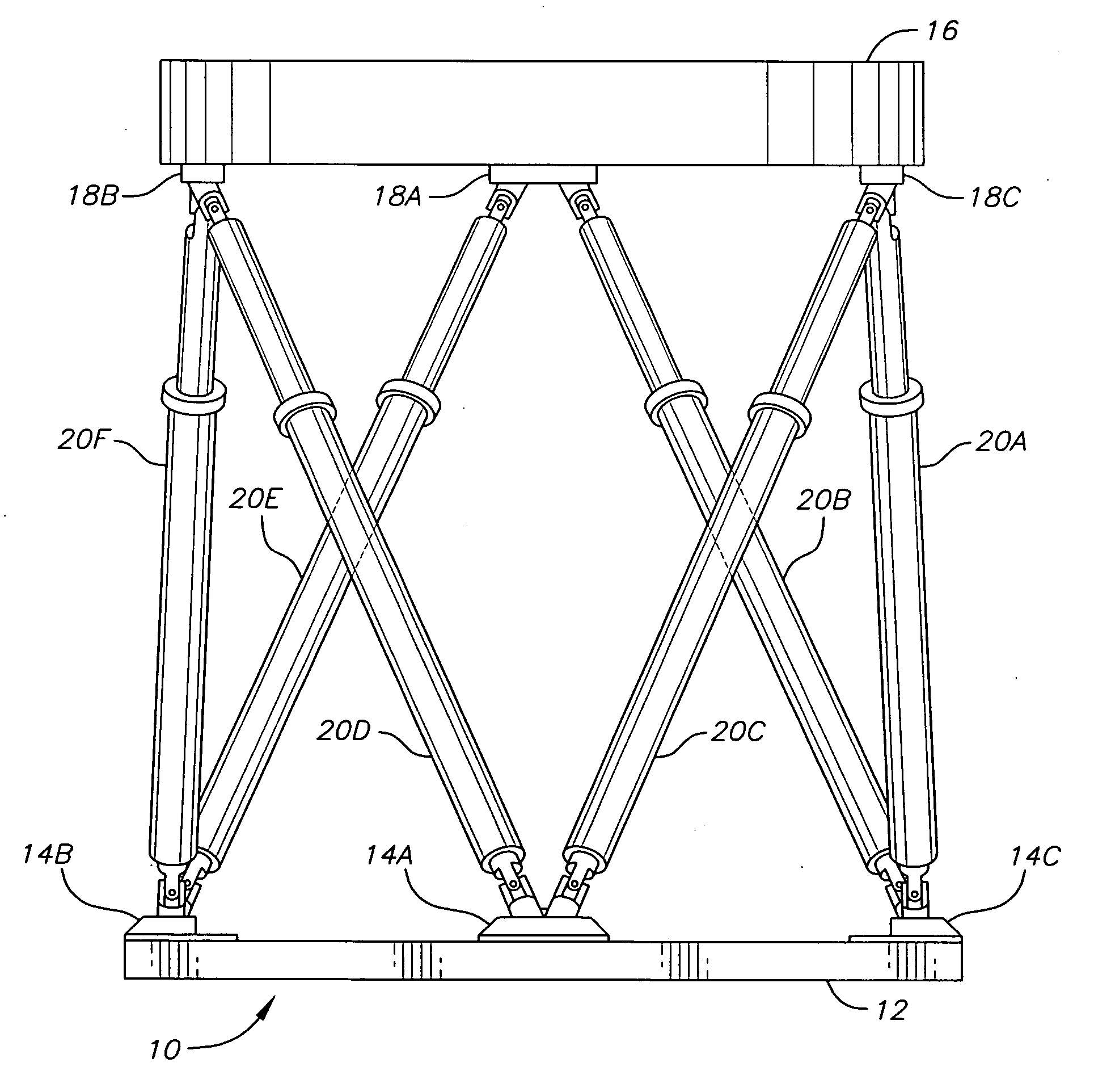
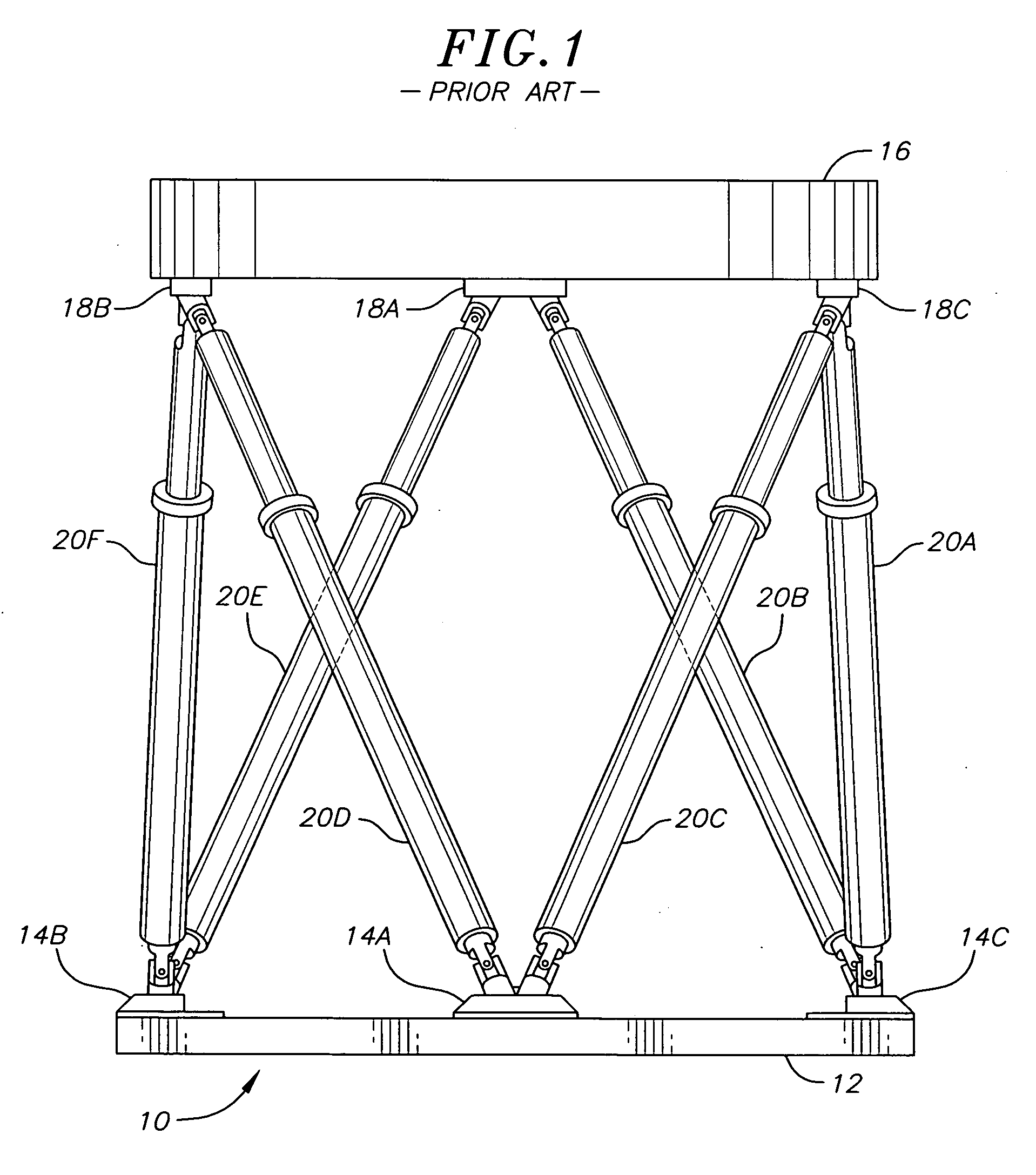
[0015] Referring to FIG. 1, there is shown a prior art motion base 10, which has a base portion 12 with three lower anchors, 14A, 14B and 14C, a floating platform portion 16 with upper anchors 18A, 18B and 18C. Six hydraulic or electric cylinders 20A through 20F connected between the lower anchors 14A, 14B and 14C to the upper anchors 18A, 18B and 18C of the floating platform 16. Cylinder 20A connects at its bottom via a universal joint to anchor 14C and at its top to the anchor 18C, also with a universal joint or other pivot. Cylinder 20B connects at its bottom portion to anchor 14C and at its top to anchor 18A by a universal joint or other pivot. The other cylinders are similarly connected. Cylinder 20C connects at its bottom portion to anchor 14A and at its top to anchor 18C. Cylinder 20D connects at its bottom portion to anchor 14A and to its top to anchor 18B. Cylinder 20E connects at its bottom portion to anchor 14B and connects to anchor 18A at its top. Lastly, cylinder 20F c...


PUM


Abstract

The invention is a vehicle simulator. It includes a vehicle simulator operator environment, a vehicle simulator base, a boom connecting the vehicle simulator operator environment to the vehicle simulator base, a plurality of articulations for rotating the vehicle simulator operator environment along at least one axis of rotational motion, and a plurality of articulations for moving the vehicle simulator operator environment along at least one axis of translational motion with the boom relative to the vehicle simulator base.

Description

CROSS-REFERENCE TO RELATED APPLICATION(S) [0001] This application claims the benefit of U.S. Provisional Patent Application No. 60 / 736,743, entitled “Vehicle Simulator”, filed on Nov. 14, 2005.SUMMARY OF THE INVENTION [0002] Vehicle Motion Simulators have been available for many decades and are used for a variety of purposes including for training of operators of military and commercial motor vehicles, heavy machinery and aircraft. For example, there are variety of flight simulators for helicopters, jets and propeller aircraft, as well as driver training simulators for trucks, boats, tanks and trains, gunnery training simulators for tanks, wheeled vehicles and boats, mission training simulators for rescue crew and drivers, and industrial simulators and material handling equipment training simulators. In addition to these uses, simulators are used in the entertainment field for a variety of amusement park rides, in museums, in video arcades, etc. [0003] Regardless of their applicatio...

Claims


Application Information

Patent Timeline
IPC IPC(8): G09B9/02G09B19/16
CPCA63G31/16G09B9/02G09B9/04G09B9/05G09B9/16G09B19/16
Inventor LEFTON, NORMAN
Owner LEFTON NORMAN
Learn More