Vessel and method for treating contaminated water

a technology for treating vessels and water, applied in water/sludge/sewage treatment, flotation, filtration separation, etc., can solve the problems of requiring substantial retention times, ineffective removal of oil droplets less than 50 microns, and often contaminated water produced by various commercial and industrial processes, etc., to achieve a high degree of control over gas rates/ratios, short lead time, and elimination of mechanical oil skimming equipment/steps

Active Publication Date: 2007-05-24
EXTERRAN WATER SOLUTIONS ULC
View PDF16 Cites 37 Cited by
  • Summary
  • Abstract
  • Description
  • Claims
  • Application Information

AI Technical Summary

Benefits of technology

[0020] The water treatment vessel preferably comprises at least two chambers (most preferably substantially of equal volume), the at least two chambers in fluid communication by means of at least one connecting pipe, the at least one connecting pipe for allowing the cleaned water to pass from the bottom of a first of the at least two chambers to a point adjacent the inlet weir of an adjacent second of the at least two chambers, the cleaned water outlet generally at the bottom of a last of the at least two chambers. The vessel also preferably comprises gas bubble injection means in fluid communication with the at least one connecting pipe for selectively injecting gas bubbles at a location in the at least one connecting pipe spaced from the inlet weir of the adjacent second of the at least two chambers, the gas bubbles preferably being microbubbles (most preferably each being less than 50 microns in diameter) composed of a gas selected from the group consisting of air, hydrocarbon gas, and nitrogen. The two adjacent chambers of the at least two chambers are preferably separated by a substantially vertical wall for separating fluids contained in each of the two adjacent chambers, with the substantially vertical wall extending from a lower inner surface of the water treatment vessel toward but spaced from an upper inner surface of the water treatment vessel, for containing fluids in each of the two adjacent chambers while allowing gas exchange between the two adjacent chambers. The at least one connecting pipe preferably passes through the substantially vertical wall and enables fluid communication between the two adjacent chambers.
[0065] Accordingly, the present invention seeks to provide a water treatment vessel and method that requires a minimal retention period, removes oil droplets less than 50 microns in diameter, and can handle solids, flow rate fluctuations, and oil concentrations of greater than 300 ppm. Vessels according to the present invention can also be manufactured with a relatively small footprint, without any moving parts, and the technology can be used for retrofit of existing tanks.

Problems solved by technology

Water produced by various commercial and industrial processes is often contaminated, particularly by oil and solid materials as is the case in the downstream petroleum industry, or may disadvantageously contain different component phases.
While such separators can be quite effective in removing larger oil droplets, however, they are generally ineffective in removing oil droplets of less than 50 microns (even if chemical treatments are added) and require substantial retention times.
This allows for vessels with a much smaller footprint than with traditional gravity separation vessels, but it has the same limitation of being generally ineffective in removing oil droplets of less than 50 microns.
In addition, chemical usage is increased and CPI vessels usually cope poorly with flow surges.
While IGF is one of the most prevalent technologies presently in use, it is still limited in terms of the oil droplet size that can be removed, and chemical treatment is therefore required.
Also, the technology generally cannot be efficiently employed in retrofit situations.
One limitation of ISF systems is that they have difficulty coping with oil concentrations above 300 ppm.
In addition, such systems do not adequately address flow rate fluctuations, and retrofit capability is generally absent.
However, hydrocyclones are used in groupings based on flow rate, and the system cannot cope well with flow rate changes and the resultant fluid velocity shift.
Also, there is a substantial pressure drop across the system, and a separate system is required to remove any solids in the produced water.
Solids blockages can also be a problem, and the solids themselves can result in significant wear of the tube interior.
While very effective in removing solids and enabling oil / water separation, the low flow rates and susceptibility to wear are problematic.

Method used


Image

  • Vessel and method for treating contaminated water
  • Vessel and method for treating contaminated water
  • Vessel and method for treating contaminated water

Examples


Embodiment Construction

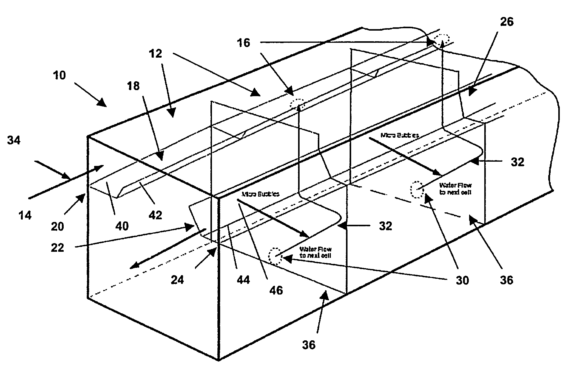
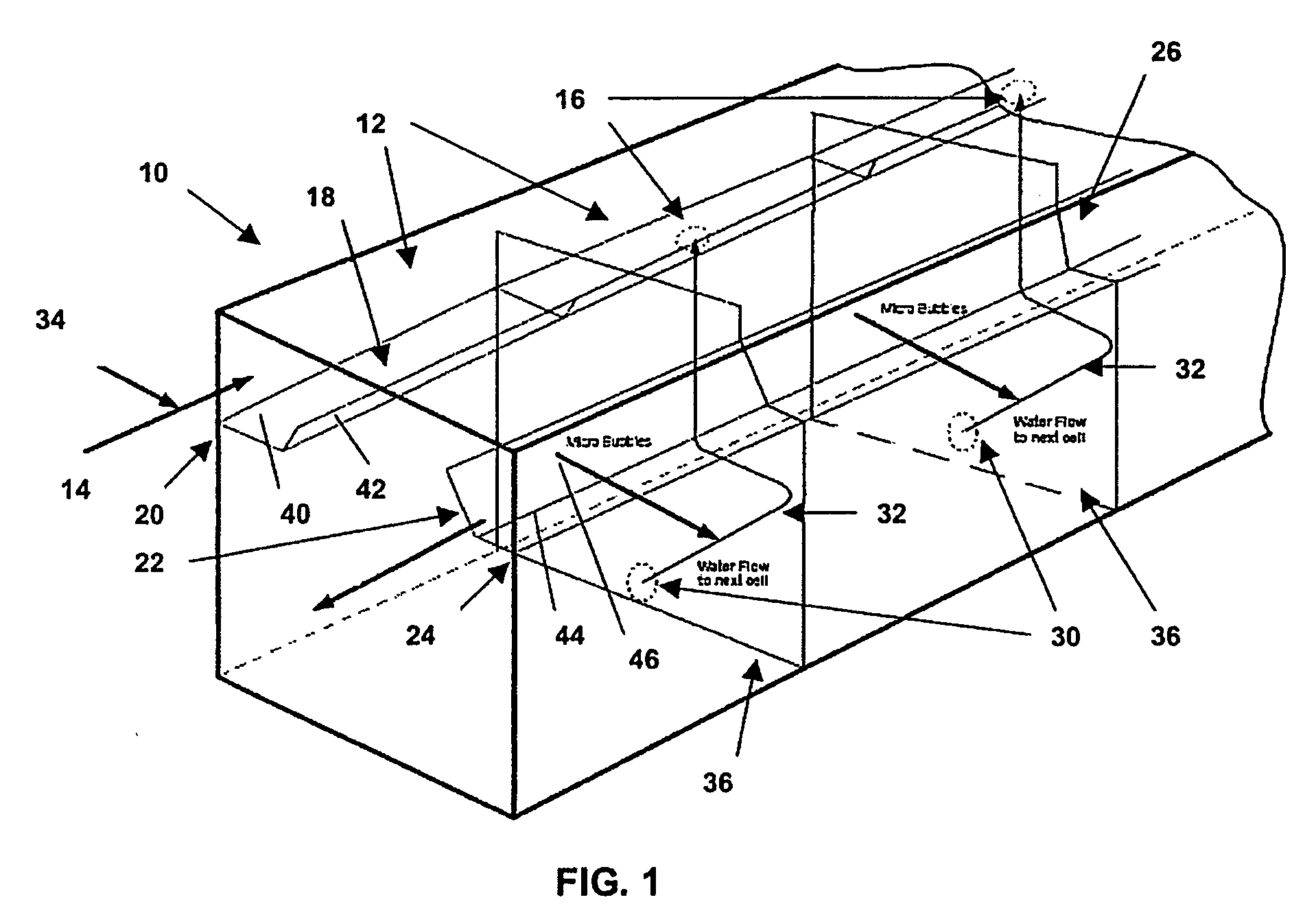
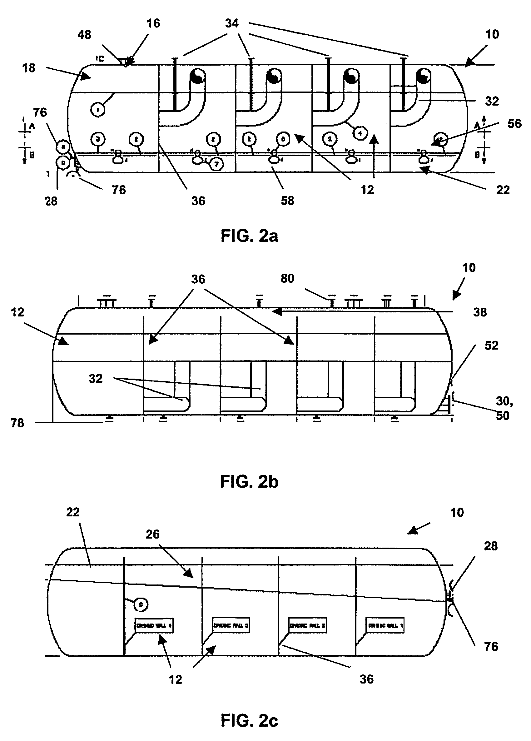
[0101] Referring now in detail to the accompanying drawings, there are illustrated several exemplary embodiments of water treatment vessels according to the present invention, each water treatment vessel generally referred to by the numeral 10. Referring specifically to FIG. 1, a simplified perspective view of a horizontally disposed vessel 10 is presented (this particular embodiment is rectangular in shape, although other shapes are possible, including some which are specifically addressed herein). The vessel 10 is divided into chambers 12 by means of vertical walls 36. An injection line 14 is in fluid communication with an inlet 16 of the first chamber 12, the injection line 14 for containing and transmitting contaminated water (not shown) from a source (not shown). The injection line 14 receives gas bubbles (not shown; preferably microbubbles, as discussed in detail below) from bubble injection means 34 which are in fluid communication with the injection line 14, allowing mixing ...


PUM

PropertyMeasurementUnit
diameteraaaaaaaaaa
temperatureaaaaaaaaaa
diameteraaaaaaaaaa

Abstract

A vessel and method for removing immiscible fluid from contaminated water, the vessel comprising: at least one chamber; an injection line in fluid communication with an inlet of the one chamber; bubble generation means in fluid communication with the injection line for injecting gas bubbles into the injection line and allowing mixing in the injection line of the gas bubbles and the contaminated water to form an inlet fluid; an inlet weir within the chamber adjacent the inlet; an immiscible fluid weir within the chamber; a trough for collecting the immiscible fluid and allowing the immiscible fluid to flow out of the at least one chamber through an immiscible fluid outlet; and a cleaned water outlet generally at the bottom of the chamber; wherein when the inlet fluid is injected into the chamber, it passes through the inlet and over the inlet weir, the cleaned water flows downwardly toward the cleaned water outlet, and a remaining mixture of the immiscible fluid and the gas bubbles floats through the chamber to pass over the immiscible fluid weir and down the trough to the immiscible fluid outlet.

Description

FIELD OF THE INVENTION [0001] The present invention relates to water treatment vessels and methods of use, and more particularly to vessels used in treating water contaminated with immiscible fluids such as oil and bitumen. BACKGROUND OF THE INVENTION [0002] Water produced by various commercial and industrial processes is often contaminated, particularly by oil and solid materials as is the case in the downstream petroleum industry, or may disadvantageously contain different component phases. Prior to discharge or re-use of this produced water, some form of treatment is generally required (either to re-use the produced water in subsequent process stages, or due to governmental regulation of discharge quality). [0003] In the context of the petroleum industry, produced water can contain small oil droplets held in suspension. Various methods and apparatus have been proposed to enable the separation of the oil from the produced water, usually employing some form of flotation system. [00...

Claims


Application Information

Patent Timeline
Patent Type & Authority Applications(United States)
IPC IPC(8): C02F1/24
CPCB01D17/0211C02F1/24C02F2101/325B01D17/0214B03D1/1406B03D1/1431B03D1/1456B03D1/1462C02F2103/10
Inventor LEE, DOUGLAS W.MUIR, GEORGE
Owner EXTERRAN WATER SOLUTIONS ULC
Why Eureka
Try Eureka