
System and method for calibrating the light source for an optical navigational system

a technology of optical navigation and light source, applied in the field of optical navigation systems, can solve problems such as damage to the human eye, and achieve the effect of reducing intensity

Active Publication Date: 2007-05-24
PIXART IMAGING INC
View PDF4 Cites 5 Cited by
  • Summary
  • Abstract
  • Description
  • Claims
  • Application Information

AI Technical Summary

Benefits of technology

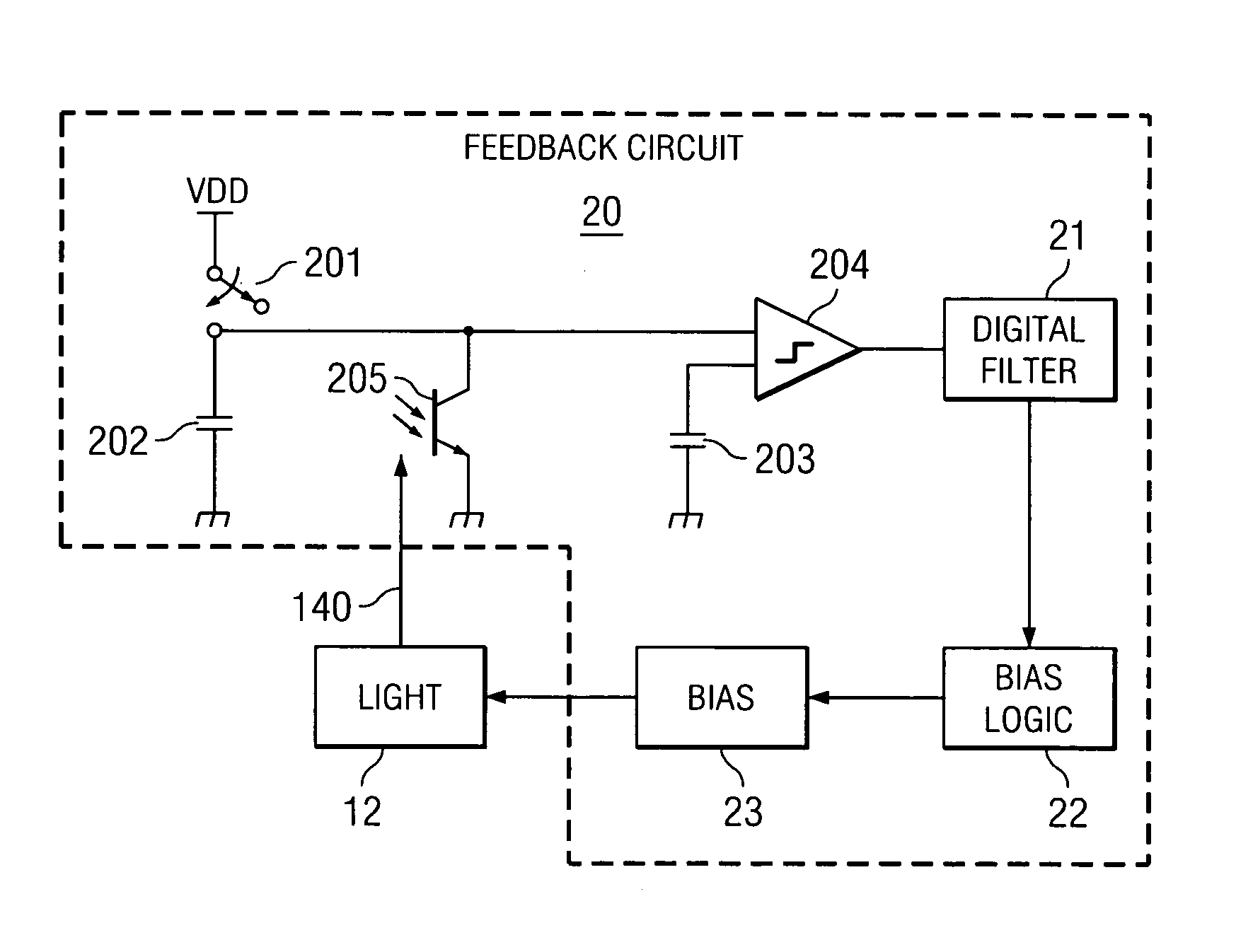
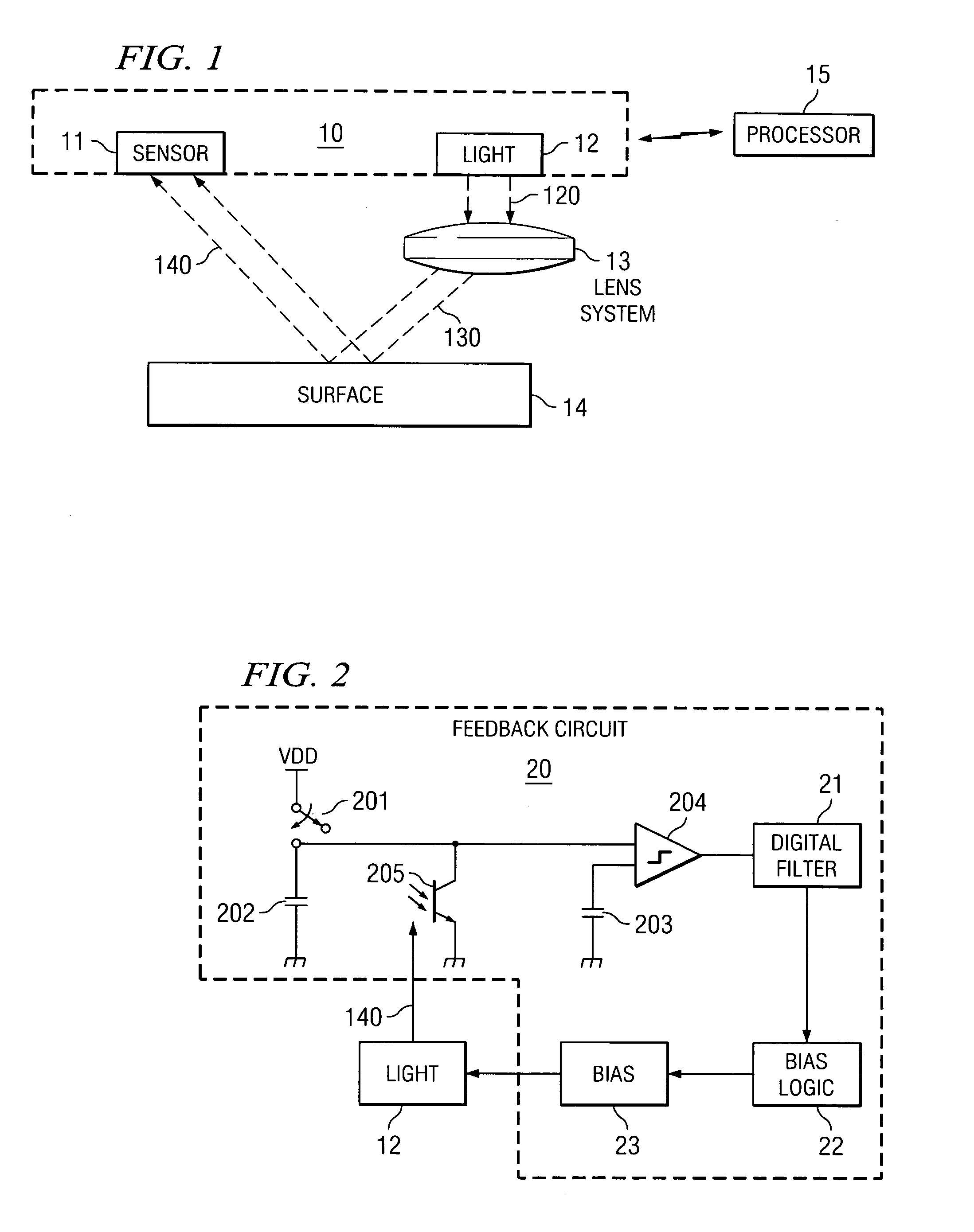
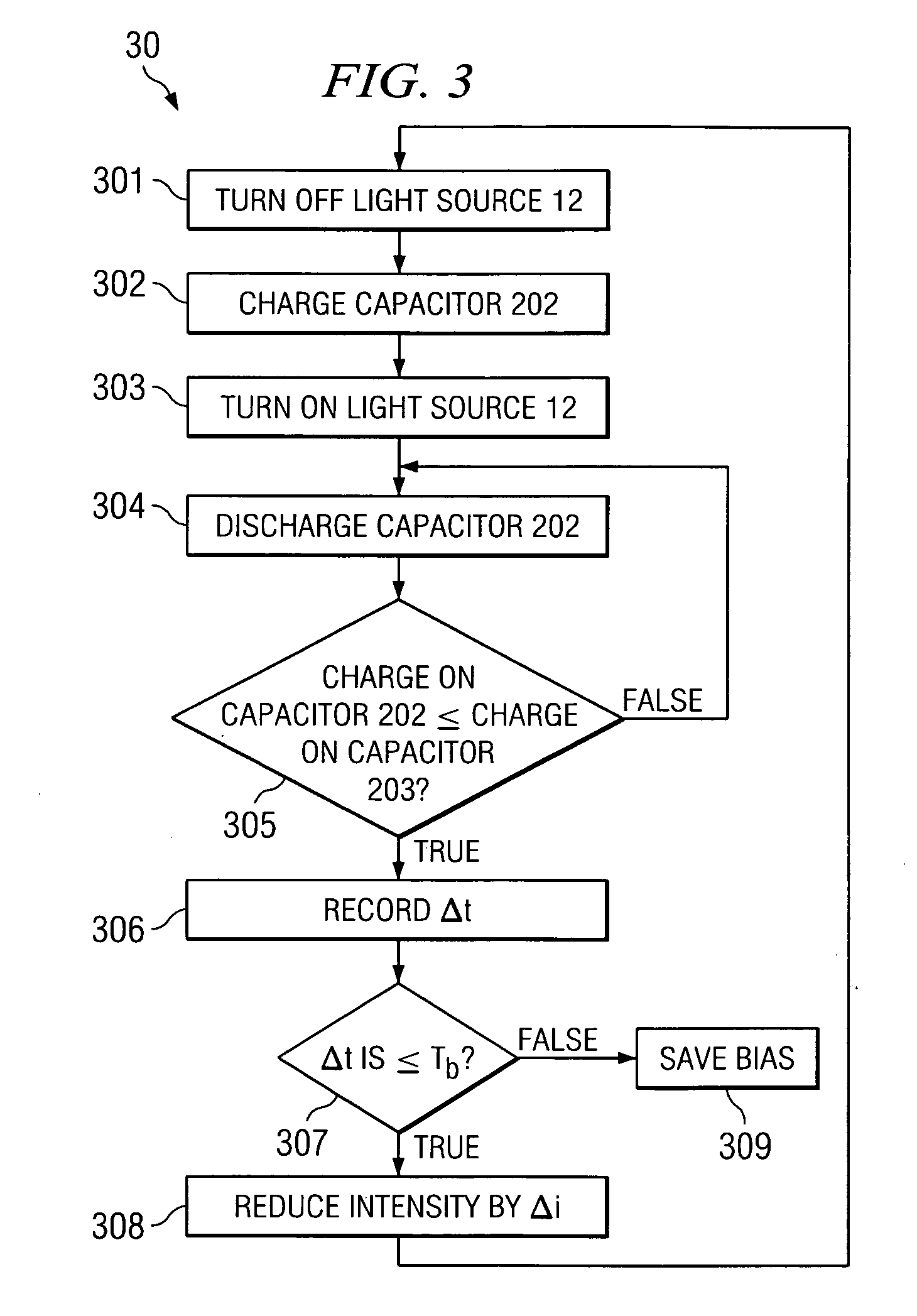
[0005] Advantage is taken of the fact that in optical navigation devices it is possible to measure the intensity of light impacting the pixel array of photo-diodes. Based upon such an intensity determination, a feedback signal is used to reduce the intensity of the light to a point where it is equal to or less than a predetermined value. In one embodiment, the discharge rate of a capacitive power supply is used to determine the intensity of the light source impacting the pixels. When the discharge rate is faster than a given amount the inference is that the light intensity is too great and power is reduced to the light source to reduce the intensity.

Problems solved by technology

Since coherent light does not degrade with distance, if the light intensity is too great it can damage the human eye.

Method used


Image

  • System and method for calibrating the light source for an optical navigational system
  • System and method for calibrating the light source for an optical navigational system
  • System and method for calibrating the light source for an optical navigational system

Examples


Embodiment Construction

[0010]FIG. 1 is a simplified schematic side view of an embodiment of an optical navigation device 10 having light source 12 and pixel array (sensor) 11. The optical device may be located on a single integrated circuit such as circuit 10, wherein light channel 120 from light source 12 passes through lens 13 becoming light channel 130. Light channel 130 reflects from surface 14 becoming light channel 140, which then impacts upon sensor 11. Sensor 11 is any well-known sensor that operates to allow for the calculation of navigational movement by picking up reflected imperfections from a surface by a light beam projected onto the surface as the navigational device moves in relation to the surface.

[0011] If desired, surface 14 may be a prism or partially mirrored surface advantageously chosen to reduce (or otherwise modify) the intensity of light impacting sensor 11 to aid the adjustment process. Navigation device 10 can work, for example, in conjunction with processor 15.

[0012]FIG. 2 i...


PUM


Abstract

Advantage is taken of the fact that in optical navigation devices it is possible to measure the intensity of light impacting the pixel array of photo-diodes. Based upon such an intensity determination, a feedback signal is used to reduce the intensity of the light to a point where it is equal to or less than a predetermined value. In one embodiment, the discharge rate of a capacitive power supply is used to determine the intensity of the light source impacting the pixels. When the discharge rate is faster than a given amount the inference is that the light intensity is too great and power is reduced to the light source to reduce the intensity.

Description

TECHNICAL FIELD [0001] This invention relates to optical navigation systems and more particularly to systems and methods for calibrating the light source of such devices to be sure that coherent light from the device does not damage humans. BACKGROUND OF THE INVENTION [0002] It is now common practice that navigation devices (sometimes called a mouse) use coherent light (laser light) to illuminate the surface for navigation purposes. The coherent light reflects from surface imperfections onto a photo-detector array (pixels) thereby providing outputs from the array which are in turn used to determine the direction of movement of the device. [0003] Since coherent light does not degrade with distance, if the light intensity is too great it can damage the human eye. Thus, during manufacture of device using coherent light (such as optical navigation devices) it is necessary to limit the light intensity to a level equal to or less than (≦) a fixed level. This is typically accomplished by l...

Claims


Application Information

Patent Timeline
Patent Type & Authority Applications(United States)
IPC IPC(8): G01J1/32
CPCG01J1/32G01J1/4228G01J1/44G01J2001/0285G06F3/0317
Inventor LIM, YEONG CHUAN
Owner PIXART IMAGING INC
Learn More