
Power line communication apparatus, power line communication method and communication apparatus

Active Publication Date: 2007-05-24
PANASONIC CORP
View PDF31 Cites 46 Cited by
  • Summary
  • Abstract
  • Description
  • Claims
  • Application Information

AI Technical Summary

Benefits of technology

[0012] An object of the present invention is to provide a power line communication apparatus, a power line communication method, and a communication apparatus that are capable of ensuring quality communication, even in multicast communication via a PLC network on which a communication status is prone to fluctuate.
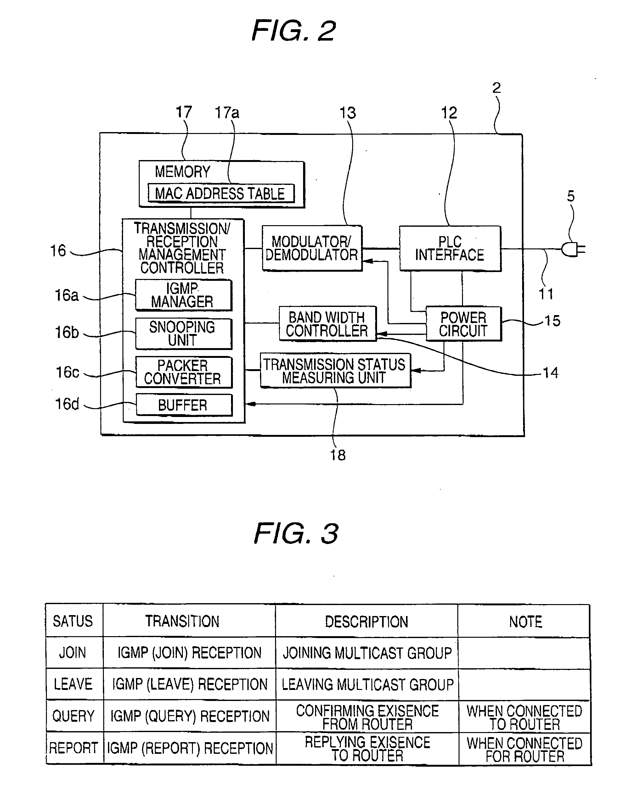
[0014] An aspect of the present invention provides the power line communication apparatus connectable to the power line to which the another power line communication apparatus is connected. The power line communication apparatus includes: the receiver that receives the packet having the first address used for multicast as the destination address; the packet converter that converts the destination address of the packet received by the receiver into the second address used for unicast; the modulation scheme determining unit that determines the modulation scheme in accordance with the status of the power line between the power line communication apparatus and the another power line communication apparatus; and the packet transmitter that transmits to the another power line communication apparatus, the packet whose destination address is converted to the second address by the packet converter, based on the modulation scheme determined by the modulation scheme determining unit. The power line communication apparatus selects a suitable modulation scheme according to the power line status, thus capable of switching multicast communication to unicast communication within a PLC network. Even when a transmission rate is limited on the PLC network, the power line communication apparatus prevents video and audio distortion caused by the limit, and thus ensures quality communication.
[0016] The configuration above allows communication using the transmission scheme determined based on the reception status of the receiving communication apparatuses, thus enabling efficient distribution of the data for multicast communication.

Problems solved by technology

In PLC, however, the power lines are not originally designed for data communication.
Further, noise, reflection, attenuation, and the like cause data loss, thus resulting in traffic slowdown, transfer delay, and the like, and, in stream distribution, video and audio distortion and communication quality degradation.
Using two types of packets, an original packet and a duplicate packet, the PLC modem distributes risk of signal degradation and thus maintains the communication quality.
Even with such PLC modem, however, it is inevitable that communication environments where PLC modems are installed are statically and dynamically different by location on the PLC network.
It is thus impossible that one PLC modem performs quality communication at an equal transmission rate to all of the plurality of PLC modems.
In transmission of packets for TV broadcast and the like to an IP device over the PLC network, quality degradation (image distortion) has occurred in a high-bit-rate program (2 Mbps or more) due to data loss.
Although the PLC modems disclosed in the above-described publications can improve the communication quality to a certain level, the PLC modems cannot ensure the communication quality.
That is, it is impossible that one PLC modem performs quality communication at the equal transmission rate to all of the plurality of PLC modems, since the PLC modems are provided in different communication environments due to the branch wirings and electric appliances connected to the power lines.
Therefore, image and sound are inevitably distorted in the high-bit-rate program due to quality degradation caused by data loss, when the packets for TV broadcast and the like on the IP network are transmitted to the IP device via the PLC network.

Method used


Image

  • Power line communication apparatus, power line communication method and communication apparatus
  • Power line communication apparatus, power line communication method and communication apparatus
  • Power line communication apparatus, power line communication method and communication apparatus

Examples


first embodiment

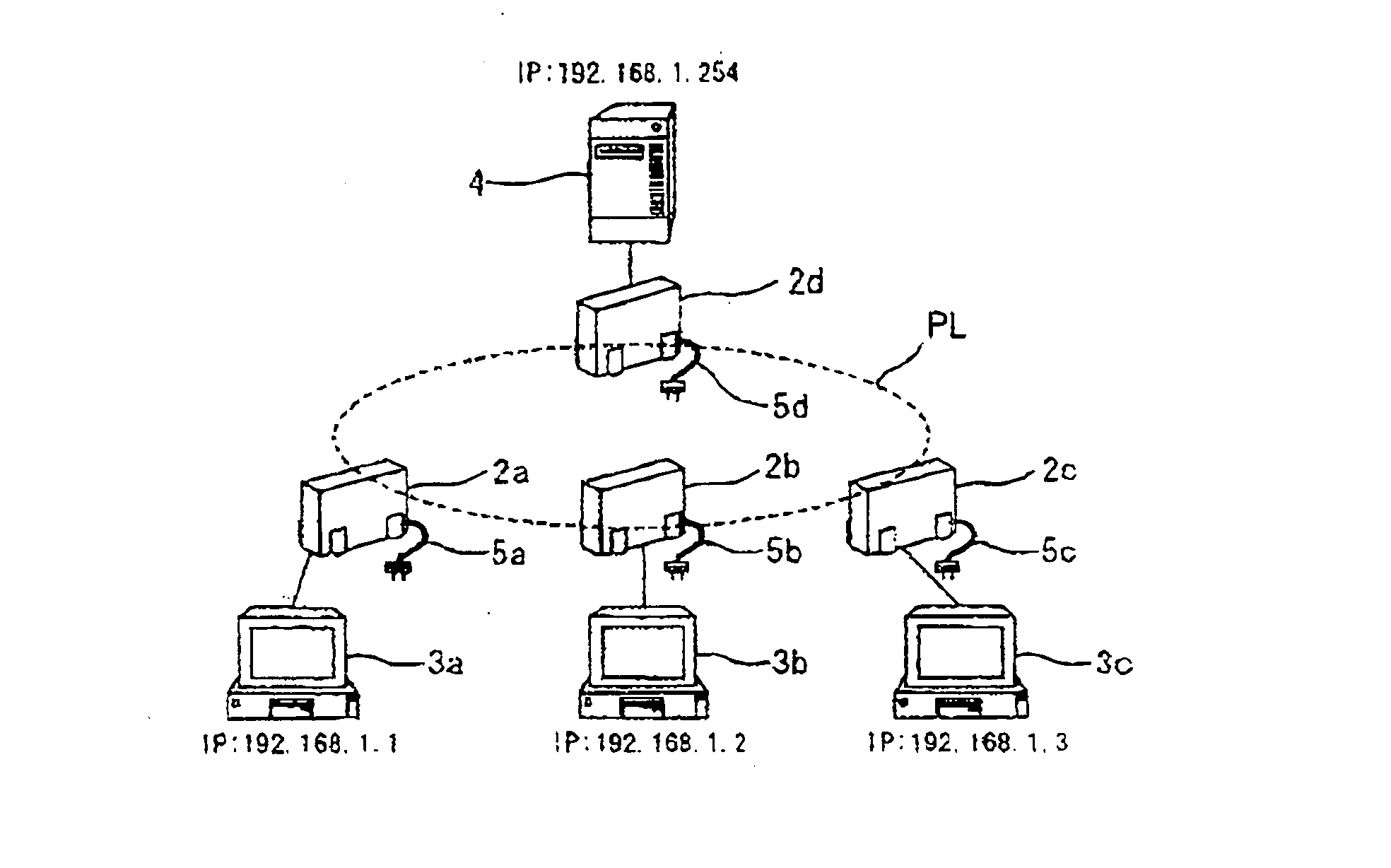
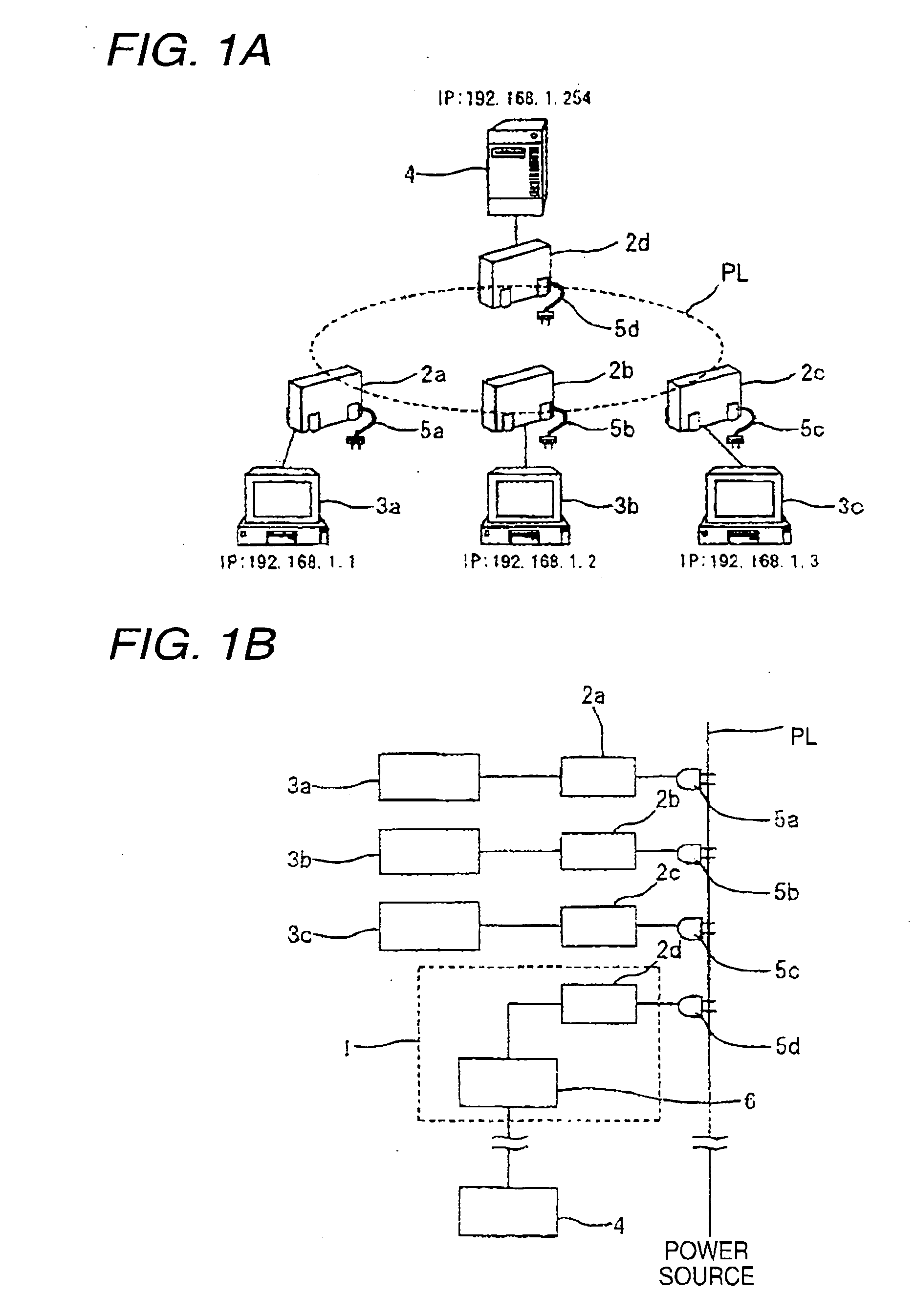
[0050] Provided below are explanations on a PLC relay device, a PLC communication system, and a PLC communication method according to a first embodiment. Shown in FIGS. 1A and 1B is power line PL, which transmits a power signal and outputs the power signal via a connector (not shown in the drawings) provided inside or outside of a building. Power line PL is also used for data communication as a transmission line on a PLC network.

[0051] Further shown are PLC modems 2a, 2b, 2c, and 2d (hereinafter collectively referred to as PLC modems 2) and IP devices 3a, 3b, and 3c (hereinafter collectively referred to as IP devices 3), which are connected to PLC modems 2. IP device 3 is provided with a set-top box (STB) capable of receiving video and audio stream distribution, or a display apparatus, such as a PC and the like, IP device 3 is not particularly limited to the STB or PC, as far as IP device 3 has a communication function that allows packet communication using an IP address. Further s...

second embodiment

[0092] The first embodiment above describes a case where, among PLC modems 2a, 2b, 2c, and 2d in the PLC communication system, PLC modem 2a receives a multicast packet. A second embodiment describes a case of multiple links where a plurality of IP devices 3a, 3b, and 3c connected to PLC modems 2a, 2b, and 2c in a PLC communication system, request stream distribution and receive a multicast packet.

[0093] When receiving IGMP (join) from PLC modems 2a, 2b, and 2c, PLC modems 2a, 2b, 2c, and 2d generate respective MAC address tables 17a through snooping. MAC address table 17a of PLC modem 2d is as shown in FIG. 11, which excludes the MAC address of PLC modem 2d. An IP address table is similar, except that a packet management key changes from the MAC address to an IP address.

[0094] Thereafter, video server 4 transmits a multicast packet to PLC modem 2d for stream distribution as shown in FIG. 11. PLC modem 2d refers to MAC address table 17a; refers to PLC MAC addresses a, b, and c of P...

third embodiment

[0100] Explained below is a third embodiment with reference to the drawings. In the third embodiment, a modem that uses a power line as a transmission line and that performs wideband communication (2 to 30 MHz) in a multicarrier communication system (a PLC modem) is used as an example of a communication apparatus.

[0101] As shown in FIG. 13, a communication system of the third embodiment includes server 500, which delivers data; and receiving terminals 600A and 600B, which receive the data delivered by the server.

[0102] Server 500 and receiving terminals 600A and 600B are connected via power lines PL. Connected between server 500 and power lines PL is communication apparatus 100X, which is an example of a transmitting communication apparatus. Connected between power lines PL and receiving terminals 600A and 600B are communication apparatuses 100A and 100B respectively, each of which is an example of a receiving communication apparatus.

[0103] Server 500 and communication apparatus ...


PUM


Abstract

PLC modems and a PLC communication system that includes the PLC modems receive a multicast packet from a video server of a multicast group. When a MAC address table is set therein, the PLC modems and the PLC communication system convert the multicast packet into a unicast packet and transmit the converted packet to a power line. When no MAC address is set, the PLC modems and the PLC communication system transmit the multicast packet to the power line.

Description

BACKGROUND [0001] 1. Field of the Invention [0002] The present invention relates to a power line communication apparatus, a power line communication method, and a communication apparatus that have a function to convert multicast communication into unicast communication and that are capable of performing power line communication (hereinafter referred to as PLC) at high quality. [0003] 2. Description of Related Art [0004] PLC that performs communication over indoor power lines has recently drawn attention. A currently proposed system even performs communication on power lines in a frequency range of 2 MHz to 30 MHz at a maximum transmission rate of over 100 Mbps in an OFDM modulation scheme, and thus a focus is on access to the Internet and the like from within a LAN and reception of video and audio stream distribution. [0005] In PLC, however, the power lines are not originally designed for data communication. In addition, a number of branch wirings are installed, and a number of elec...

Claims


Application Information

Patent Timeline
IPC IPC(8): H04L12/56H04J3/16
CPCH04B3/54H04B2203/5408H04B2203/5445H04B2203/5495
Inventor KOGA, HISAOKODAMA, NOBUTAKAYOKOMITSU, YASUSHIIGATA, YUJIHARAGUCHI, MASAHIKOYASUKAWA, TORU
Owner PANASONIC CORP
Learn More