Image processing device having color shift correcting function, image processing program and electronic camera

a technology of image processing and color shift correction, which is applied in the direction of single pick-up device signal generators, instruments, signal generators, etc., can solve the problems of detection errors, detection detection errors, and easy loss of point symmetry, so as to achieve optimal color shift correction

Active Publication Date: 2007-05-24
NIKON CORP
View PDF4 Cites 58 Cited by
  • Summary
  • Abstract
  • Description
  • Claims
  • Application Information

AI Technical Summary

Benefits of technology

[0023] In view of solving the above problems, an object of the present invention is to provide a techniq

Problems solved by technology

The inventors of the present application have found that the chrominance LPF and false color causes problems in the detection and correction of the amount of aberration disclosed in the Documents 1 and 2.
However, chrominance LPF causes unevenness in the chromatic aberration of magnification and the point symmetry is readily lost.
Detection of the amount of aberration in such a state will cause errors in the detection result.
If the chrominance LPF is removed or weakened in order to avoid the problems in the detection and correction of the above-mentioned chromatic aberration of magnification, there arises a problem in turn that the false color noises at the time of color interpolation remains as they are.
In such a state, errors are likely to occur in the detection result of the amount of aberration.
According to the Documents 1 and 2, in particular, the color shift due to chromatic aberration of magnification is corrected uniformly in the screen, therefore, it is not possible to avoid the errors.
Because of this, in a region in which the

Method used


Image

  • Image processing device having color shift correcting function, image processing program and electronic camera
  • Image processing device having color shift correcting function, image processing program and electronic camera
  • Image processing device having color shift correcting function, image processing program and electronic camera

Examples


first embodiment

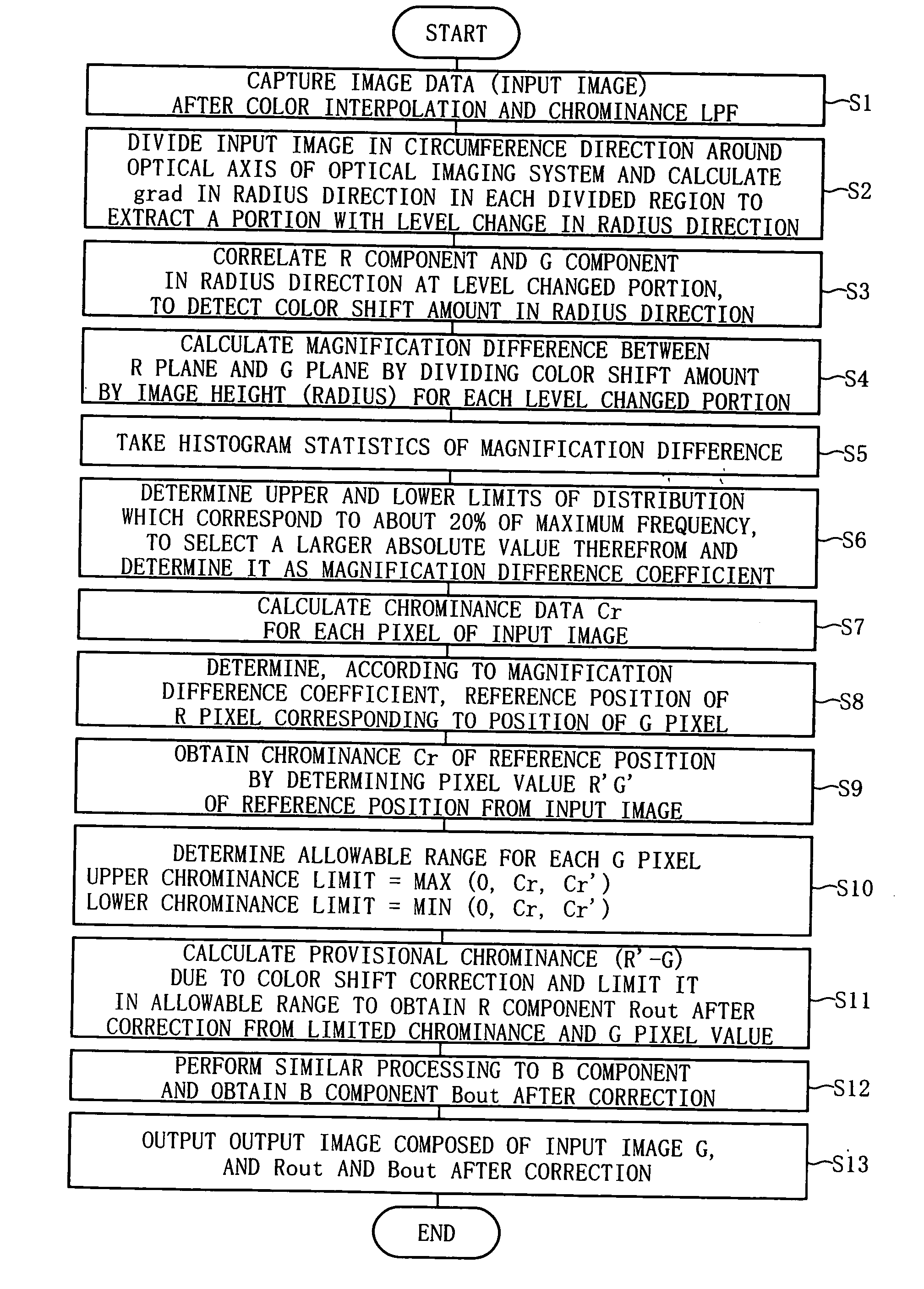
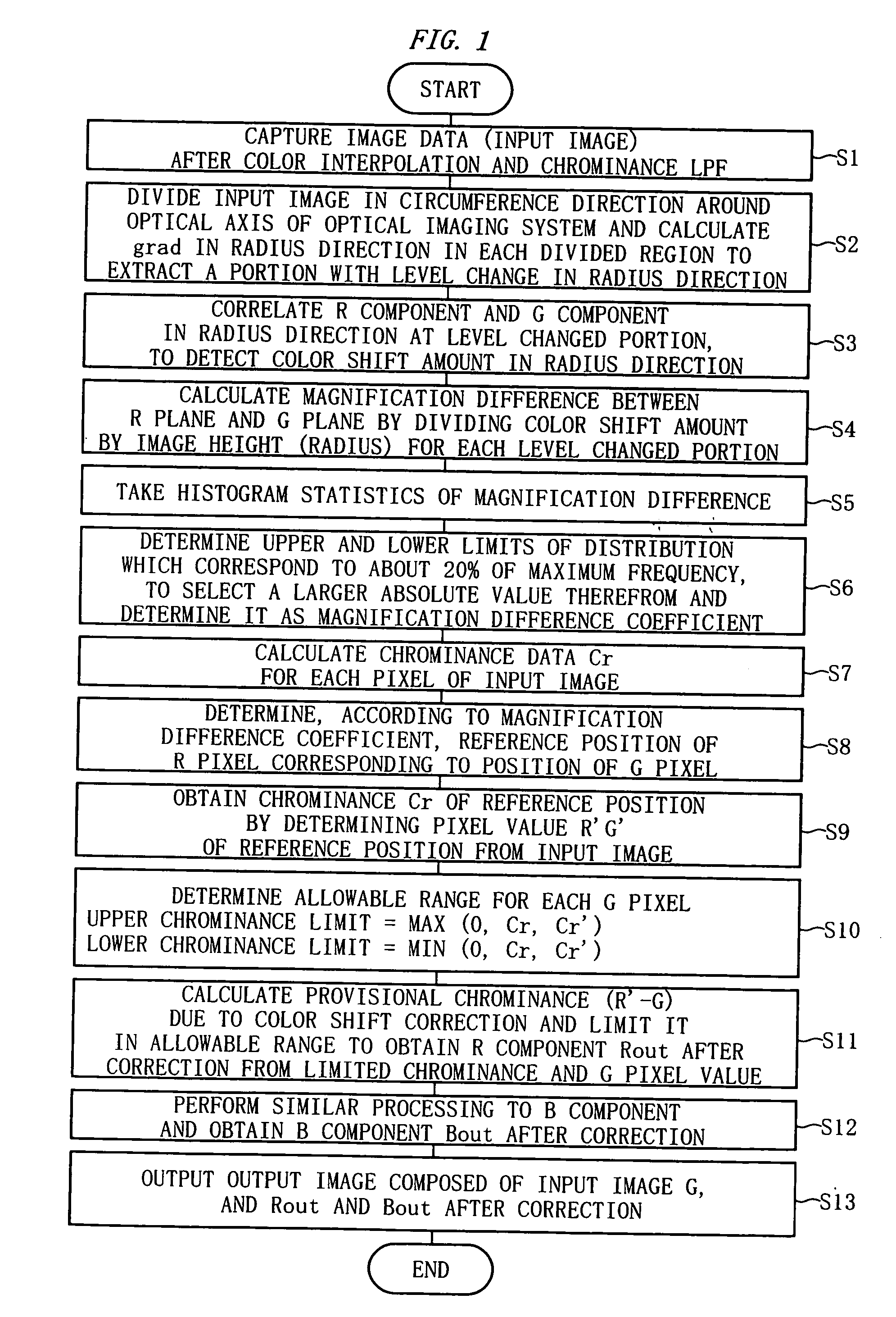
[0082]FIG. 1 is a flow chart for explaining the computer operation by an image processing program. It is possible to cause the computer to function as an image processing device by the image processing program.

[0083] The operation in a first embodiment is explained below following the step numbers shown in FIG. 1.

[0084] [Step S1]

[0085] A computer captures image data (hereinafter, referred to as an “input image”) shot by an electronic camera via a recording medium or a communication interface. The input image has already been subjected to color interpolation and chrominance LPF in the electronic camera.

[0086] [Step S2]

[0087] The computer sets an optical axis center of an optical imaging system in the screen of the input image. Usually, the screen center of the input image is set as an optical axis center by default. In addition, it may also be possible for the computer to acquire the position of the optical axis center from attached information (Exif information etc.) of the input...

second embodiment

[0159]FIG. 7 and FIG. 8 are diagrams for explaining the second embodiment.

[0160] In general, the optical axis center of an optical imaging system is located substantially at the screen center of image data. Because of this, usually, the chromatic aberration of magnification is produced in a point symmetric manner with respect to the screen center.

[0161] However, in some of optical imaging systems (shift lenses or hand movement compensated lenses), the optical axis center of the optical imaging system does not necessarily coincide with the screen center of image data. Further, a case is supposed where the optical axis center of an optical imaging system comes not to coincide with the screen center of image data any longer after the image data is subjected to trimming (cropping) by processing on an electronic camera or a computer. If any manufacture error should occur in a lens, there is the possibility that the chromatic aberration of magnification is not produced in a point symmet...

third embodiment

[0170] The third embodiment describes a computer equipped with the image processing function of the present invention.

[0171] As shown in FIG. 9, a computer 10 includes a control part 1, an external interface part 2, and an operation part 3. The control part 1 records in advance a program for performing the image processing of the present invention. Further, the external interface part 2 interfaces with an external device such as an electronic camera via a predetermined cable or a radio channel. The operation part 3 is equipped with a keyboard, a mouse, etc., although not shown.

[0172] In the computer 10 having a configuration as shown in FIG. 9, it is possible for the external interface part 2 to capture an image from an external device such as an electronic camera, not shown, in accordance with the direction of the control part 1. The operation part 3 accepts various user operations. The state of the operation part 3 is detected by the control part 1.

[0173]FIG. 10 shows a rough f...


PUM


Abstract

An image processing device performs image processing to an image represented by a plurality of color component planes and includes a correction unit and an erroneous correction detection unit. The correction unit corrects a color shift in the image. The erroneous correction detection unit judges that the correction unit has made an erroneous correction by comparing the images before and after the correction. More preferably, the erroneous correction detection unit judges the erroneous correction when a chrominance of a portion to be processed of the image after the correction is not within an allowable range which is set using the image before the correction as a reference.

Description

CROSS REFERENCE TO RELATED APPLICATION [0001] This application is a continuation application of International Application PCT / JP 2005 / 006951, filed Apr. 8, 2004, designating the U.S., and claims the benefit of priority from Japanese Patent Application No. 2004-116584, filed on Apr. 12, 2004 and No. 2004-161474, filed on May 31, 2004, the entire contents of which are incorporated herein by reference.BACKGROUND OF THE INVENTION [0002] 1. Field of the Invention [0003] The present invention relates to an image processing device, an image processing program, and an electronic camera. [0004] 2. Description of the Related Art [0005] In general, in an electronic camera, it is known that a color shift occurs in captured image data due to the chromatic aberration of magnification of an optical imaging system. There has been proposed of a conventional technique to correct such a color shift by image processing. [0006] For example, a conventional device disclosed in Japanese Unexamined Patent A...

Claims


Application Information

Patent Timeline
IPC IPC(8): G06K9/40H04N9/04H04N9/07
CPCH04N25/611
Inventor UTSUGI, AKIHIKOISHIGA, KENICHI
Owner NIKON CORP
Why Eureka
Try Eureka