Eletric power steering system

a technology of electric power steering and steering wheel, which is applied in the direction of steering initiation, instruments, vessel construction, etc., can solve the problems of system destabilization (or is prone to vibration), driver may experience a loadless steering feeling, and drawbacks even more significant, so as to achieve reliable stability and improve response

Inactive Publication Date: 2007-05-24
JTEKT CORP
View PDF3 Cites 22 Cited by
  • Summary
  • Abstract
  • Description
  • Claims
  • Application Information

AI Technical Summary

Benefits of technology

[0023] Since the parameter ω1 as the compensated natural angular frequency is smaller than the angular frequency ωm of the natural vibrations of the mechanical system, the control system is prevented from being destabilized by the natural vibrations of the mechanical system. Thus, the control system may more reliably maintain stability and achieve the improved response.

Problems solved by technology

Unfortunately, the electric power steering system includes a mechanical resonant system including a spring element constituted by a torsion bar and an inertial element constituted by the electric motor, the torsion bar interposed in a steering shaft for detecting the steering torque.
Therefore, if the PI gain value is increased too much, the system tends to suffer destabilization (or is prone to vibrations) at resonant frequencies of the resonant system, which are near natural frequencies of the mechanical system of the electric power steering system (specifically, in the range of 10 to 25 Hz).
During driving, however, the great phase lag in the low-frequency region degrades steering feeling in a low-load region corresponding to a neighborhood of a neutral position of the handle, so that the driver may experience a loadless steering feeling.
What is worse, this drawback is even more significant in a high-efficiency electric power steering system featuring low friction.
However, the system disclosed in Japanese Unexamined Patent Publication No.
That is, this system does not differentiate between steering assist during steer without driving or when a vehicle speed V is at zero, and steering assist during driving.
Hence, the system does not overcome the above problem related to the phase compensator whose characteristics are defined based on the steer-without-driving assist characteristic.

Method used


Image

  • Eletric power steering system
  • Eletric power steering system
  • Eletric power steering system

Examples


Embodiment Construction

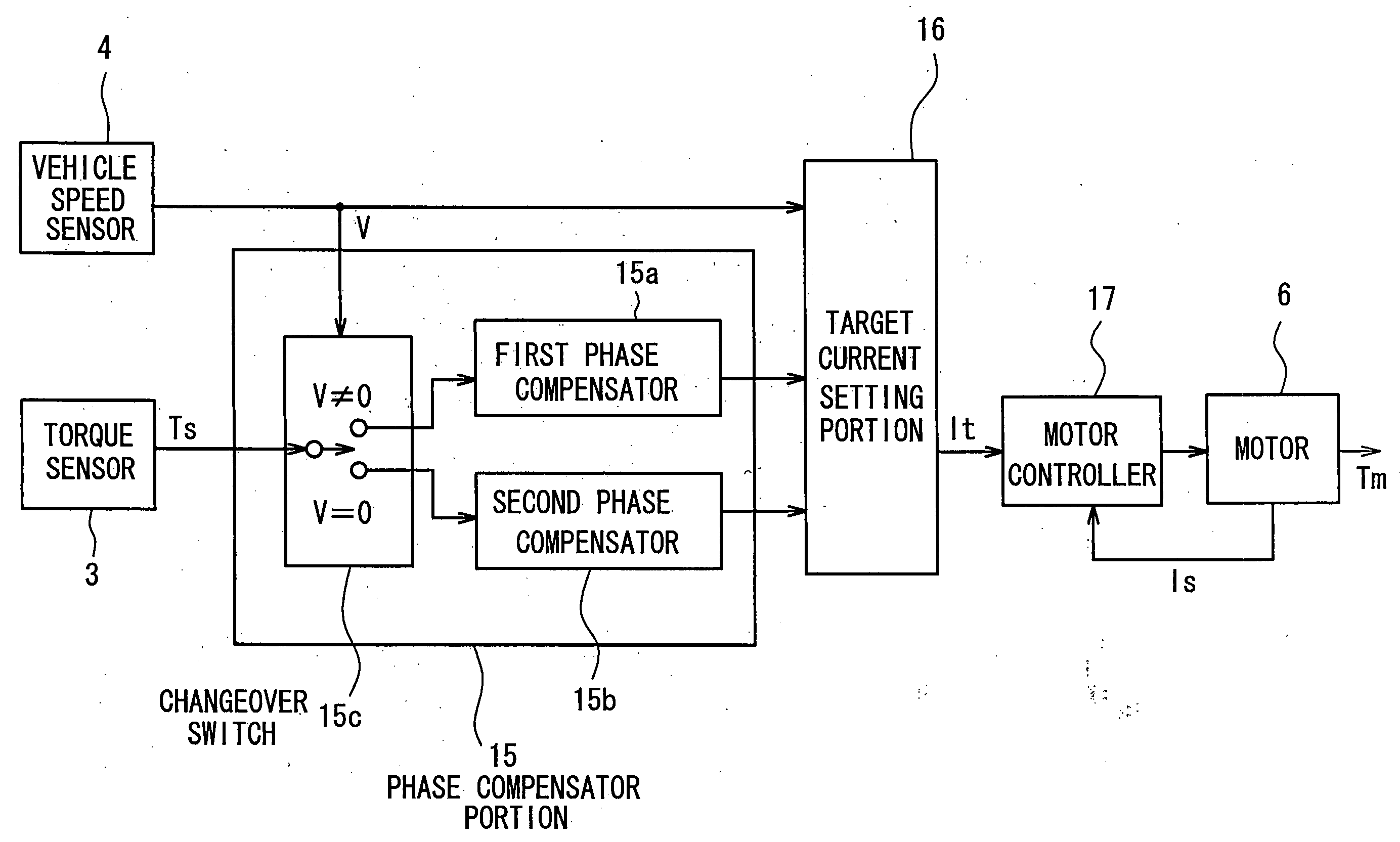
[0035] First, a basic study for phase compensation design will be described.

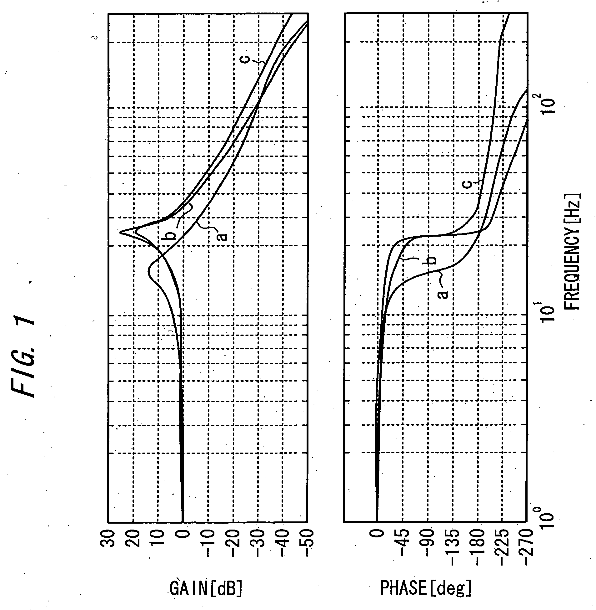
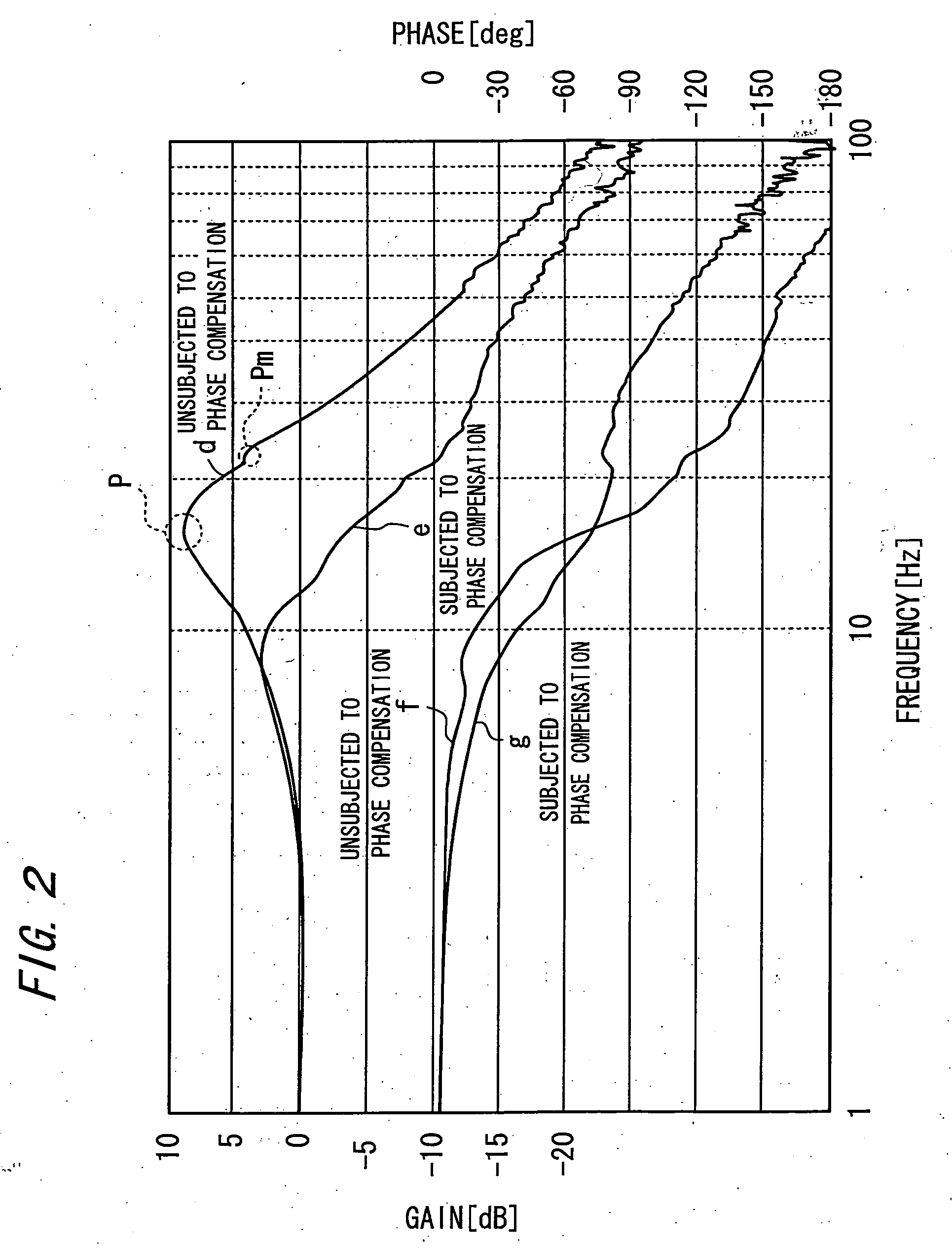
[0036] The aforementioned conventional technique related to the phase compensation in the control design for the electric power steering system has been proposed as a measure for compensating for a peak of natural vibration frequencies of a mechanical system (hereinafter, referred to as “mechanical-system peak”) , which are mechanical resonant frequencies. However, the technique does not consider an influence of a counter-electromotive force of a motor. According to the conventional technique, a peak of a system gain characteristic of the electric power steering system or of a gain characteristic of open-loop transfer function for torque (hereinafter, referred to as “system peak”) is regarded as the peak of the mechanical system. However, the results of the following simulation revealed that the counter-electromotive force in the motor exerts such a significant influence on the characteristics of the system...


PUM


Abstract

An electric power steering system causing an electric motor 6 to generate a steering assist force according to a steering torque, includes: a torque sensor 3 for detecting the steering torque; phase compensation means 15a, 15b acting when a target control value of the electric motor 6 is generated based on an output from the torque sensor 3; and means 15c for varying the characteristic of the phase compensation means depending upon whether a steering mode is steer with driving or steer without driving, whereby a loadless steering feeling due to phase lag is not encountered during driving even if vibrations during steer without driving are suppressed by a phase compensator.

Description

TECHNICAL FIELD [0001] The present invention relates to an electric power steering system. BACKGROUND ART [0002] Conventionally, the electric power steering system has been used, which applies a steering assist force to a steering mechanism by driving an electric motor according to a steering torque applied by a driver to a handle (steering wheel; steering member). [0003] The electric power steering system typically uses a proportional integrator for providing a current control (feedback control) such that a target current may flow through the electric motor, the target current defined based on a steering torque indicated by a torque detection signal from a torque sensor. [0004] Proportional gain and integral gain (hereinafter, collectively referred to as “PI gain”) of the proportional integrator may desirably have a higher value from the standpoint of increasing the response of the overall system. [0005] Unfortunately, the electric power steering system includes a mechanical resona...

Claims


Application Information

Patent Timeline
Patent Type & Authority Applications(United States)
IPC IPC(8): B62D6/00B62D5/04B62D7/22B62D101/00B62D119/00
CPCB62D5/0472B62D7/224B62D5/04B62D6/10B62D7/00B62D7/22
Inventor NISHIZAKI, KATSUTOSHIOYA, TOSHIAKISAKAMAKI, MASAHIKO
Owner JTEKT CORP
Why Eureka
Try Eureka