Heat exchanger tube panel module, and method of constructing exhaust heat recovery boiler using the same

a technology of heat exchanger tube and panel module, which is applied in the direction of steam generation using hot heat carriers, lighting and heating apparatus, nuclear elements, etc., can solve the problems of high construction cost, long work period, and enormous labor and time required for installation, and achieve the effect of short time and easy installation

Inactive Publication Date: 2007-05-31
MITSUBISHI HITACHIPOWER SYST LTD
View PDF7 Cites 41 Cited by
  • Summary
  • Abstract
  • Description
  • Claims
  • Application Information

AI Technical Summary

Benefits of technology

[0020] As mentioned above, the heat exchanger tube panel modules 25 are manufactured in a manufacturing factory, and then the modules 25 are transported to the construction site and installed on site, whereby installation of the heat exchanger tube panels 23 is completed along with the casing 1 for an HRSG, the dangerous construction work at the upper side inside the casing 1 of the HRSG is eliminated, setting up of scaffolds and dismounting thereof become unnecessary, and the heat exchanger tube panels 23 can be easily installed in the casing 1 of the HRSG within a short period of time, so that the HRSG can be constructed within a short work period.

Problems solved by technology

However, even under these circumstances, the HRSG is not small in size, and its installation requires enormous labor and time.
Such work of suspending thousands or ten of thousands of heat exchanger tubes at a high place is not only dangerous but also results in an extended work period and high construction costs.

Method used


Image

  • Heat exchanger tube panel module, and method of constructing exhaust heat recovery boiler using the same
  • Heat exchanger tube panel module, and method of constructing exhaust heat recovery boiler using the same
  • Heat exchanger tube panel module, and method of constructing exhaust heat recovery boiler using the same

Examples


Embodiment Construction

[0037] A modularization method of an exhaust heat recovery boiler as an embodiment of the invention is described with reference to the drawings.

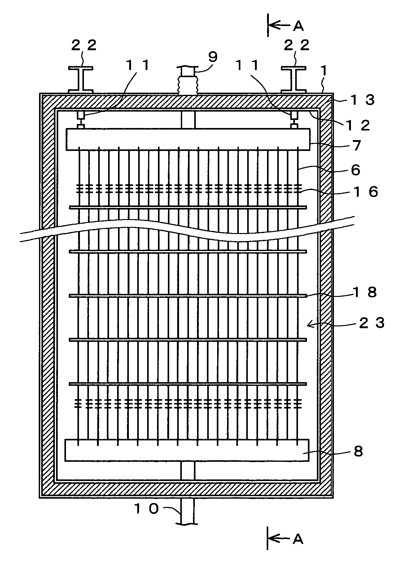
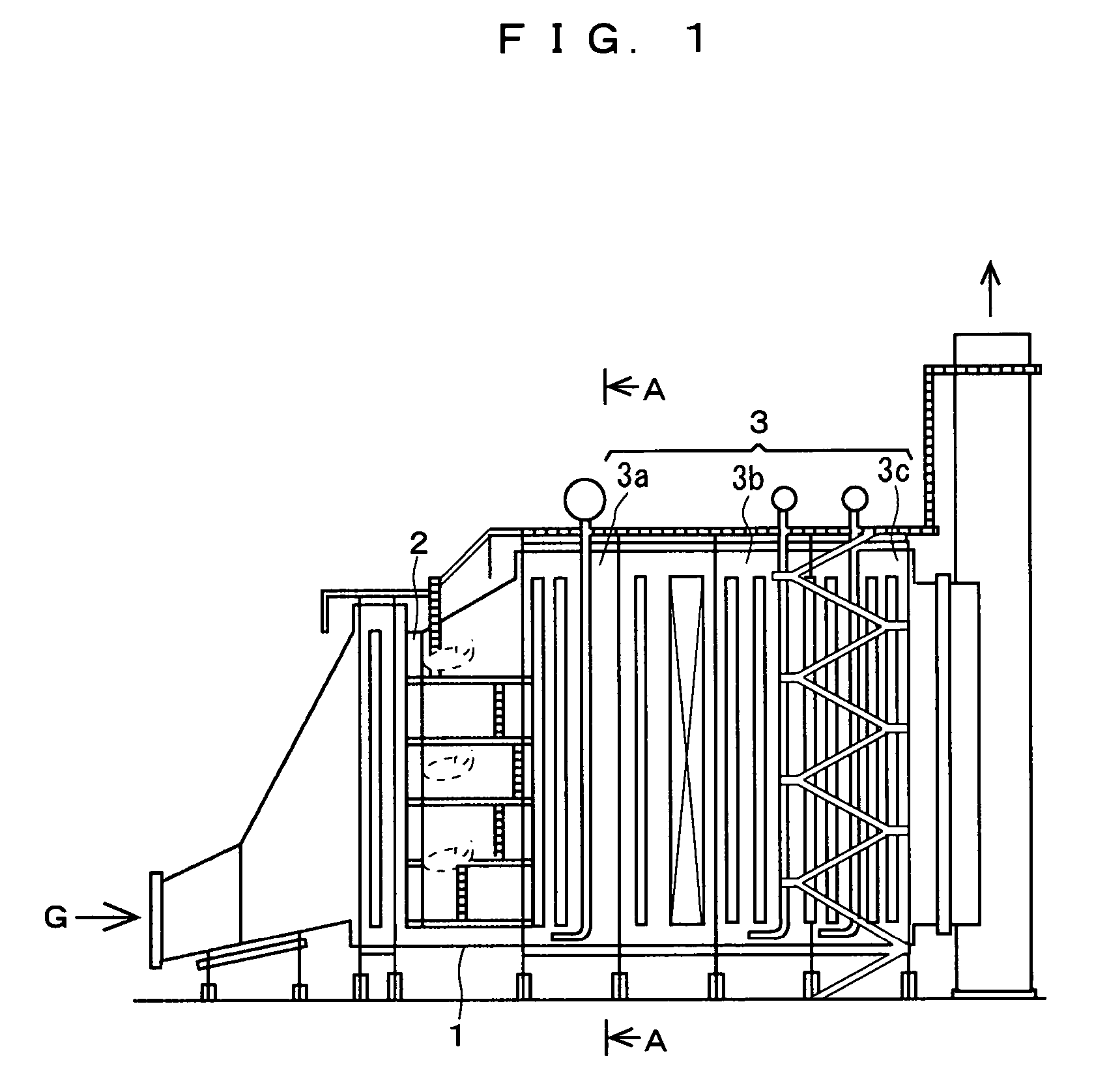
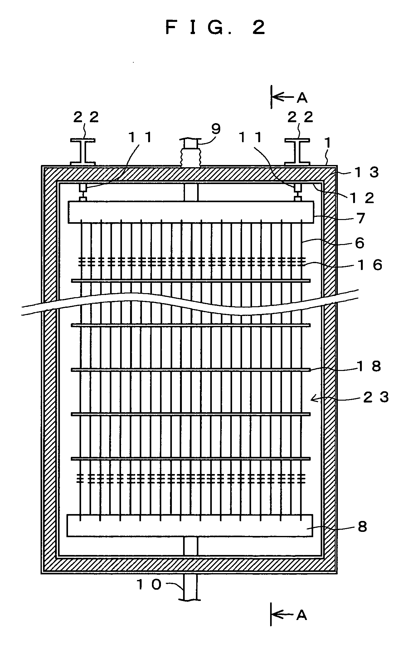
[0038]FIG. 2 shows a section orthogonal to the gas flow direction of the exhaust heat recovery boiler, and FIG. 3 shows a section in the gas flow direction of the exhaust heat recovery boiler. FIG. 2 corresponds to a sectional view of the arrow along the A-A line of FIG. 1, and FIG. 3 corresponds to a sectional view of the arrow along the A-A line of FIG. 2.

[0039] A heat exchanger tube panel 23 of the exhaust heat recovery boiler comprises, as shown in FIG. 2 and FIG. 3, heat exchanger tubes 6, upper headers 7, lower headers 8, upper connecting pipes 9, and lower connecting pipes 10, and the heat exchanger tubes 6 are supported by heat exchanger tube panel support beams 22 via header supports 11 at the upper side. The outer circumference of the heat exchanger tube panel 23 is covered by the casing 1 and an inner casing 12 and an heat insul...


PUM


Abstract

A necessary size and number of modules each obtained by housing a member including heat exchanger tube panels each comprising a heat exchanger tube bundle and headers for the heat exchanger tube bundle, an upper casing of an exhaust heat recovery boiler (HRSG), provided above the heat exchanger tube panels, heat insulators, and heat exchanger tube panel support beams provided on the upper surface of the upper casing into a transportation frame, are prepared according to design specifications of the HRSG, and side casings and a bottom casing except for the ceiling part casing are constructed in advance at a construction site of the HRSG, and the modules are suspended from above between adjacent support beams of the ceiling part to dispose the heat exchanger tube panel support beams of the modules at the set heights of the ceiling part support beams, and the support beams and the ceiling part support beams are connected and fixed via connecting steel plates, whereby the respective modules are transported to the HRSG construction site and can be easily constructed.

Description

TECHNICAL FIELD [0001] The present invention relates to an exhaust heat recovery boiler (hereinafter, referred to occasionally as HRSG) to be used for a combined cycle power plant, more specifically, an exhaust heat recovery boiler construction method (modularization method) and a heat exchanger tube panel module structure to be used with this method. BACKGROUND ART [0002] A combined cycle power plant using a gas turbine has a high heat efficiency in comparison with a thermal power plant using a coal-fired boiler, and the amount of SOx and soot and dust generated from the combined cycle power plant is small since it uses natural gas mainly as fuel, and therefore, the burden on exhaust gas purification is small, whereby the combined cycle power plant has gained attention as a power plant with great future potential. Furthermore, the combined cycle power plant is excellent in load responsibility, and has gained attention simultaneously as a power generation method which can rapidly ch...

Claims


Application Information

Patent Timeline
Patent Type & Authority Applications(United States)
IPC IPC(8): F22B37/00F22B1/18F22B37/20
CPCF22B1/1815F22B37/001F22B37/20F22B37/244
Inventor WASEDA, ISAOKAWAHARA, ATSUOMUSASHI, MITSUGISHIGENAKA, TOSHINORI
Owner MITSUBISHI HITACHIPOWER SYST LTD
Why Eureka
Try Eureka