Roof drilling improvements

a technology for roofs and drilling holes, applied in drilling machines and methods, cutting machines, mining structures, etc., can solve the problems of fracturing the cutting element, pcd cutting inserts may even shatter, and the cutting element of superabrasives can fail, so as to achieve the effect of faster drilling

Inactive Publication Date: 2007-05-31
WILLIAM J BRADY LOVING TRUST THE
View PDF9 Cites 18 Cited by
  • Summary
  • Abstract
  • Description
  • Claims
  • Application Information

AI Technical Summary

Benefits of technology

[0009] It is the principal object of the present invention to provide a hard rock boring tool with an improved heavy duty high alloy steel body and mounting shank that will extend the useful life of the tool.
[0012] Still another object is to provide a method for obviating premature tool failure in hard / soft rock drilling.
[0014] Still another object is to provide an HCD bit using PCD cutting elements and an optimum supporting body, that accommodates torsional stress, and drills faster in extremely hard / soft rock structures.

Problems solved by technology

It is well-known for example, that superabrasive (PCD) cutting elements can fail caused by the fact that the materials comprising the superabrasive portion, or diamond table, and the substrate have different coefficients of thermal expansion, elastic moduli and bulk compressibilities.
Thus the table and substrate materials of a PCD wafer shrink at different rates during cooling after formation and the diamond table tends to be in residually stressed tension while the substrate material tends to be in residually stressed compression when subjected to cutting loads during drilling operations which may result in fracturing of the cutting element.
Although these prior HCD bits drilled through such earth structures, it was discovered that some drill bits might plug in drilling through mud seams and other soft shale or broken earth formations and PCD cutting inserts may even shatter in working through stratus of extremely hard or fractured earth conditions.
My prior PCD bits are capable of achieving some success in these conditions, but drilling speeds are slow and fracturing of drill steel, couplers and drill bits frequently occurs.

Method used


Image

  • Roof drilling improvements
  • Roof drilling improvements
  • Roof drilling improvements

Examples


Embodiment Construction

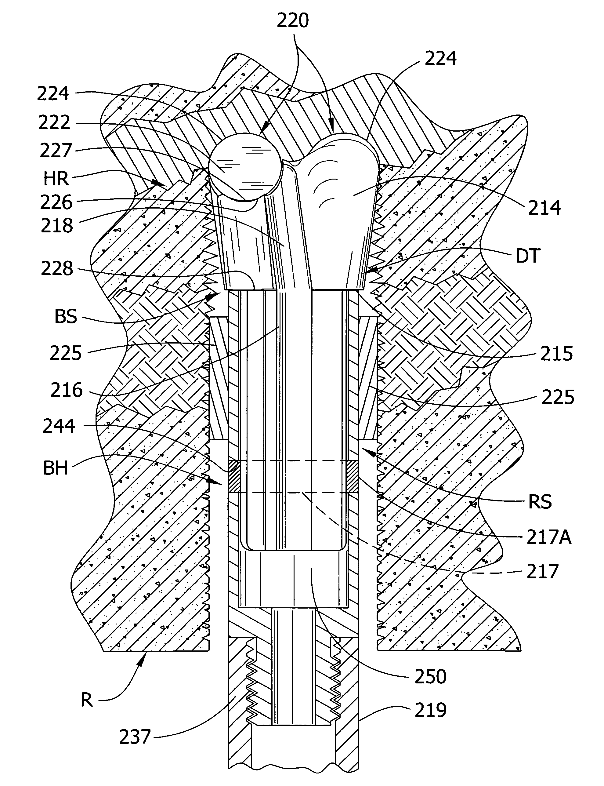
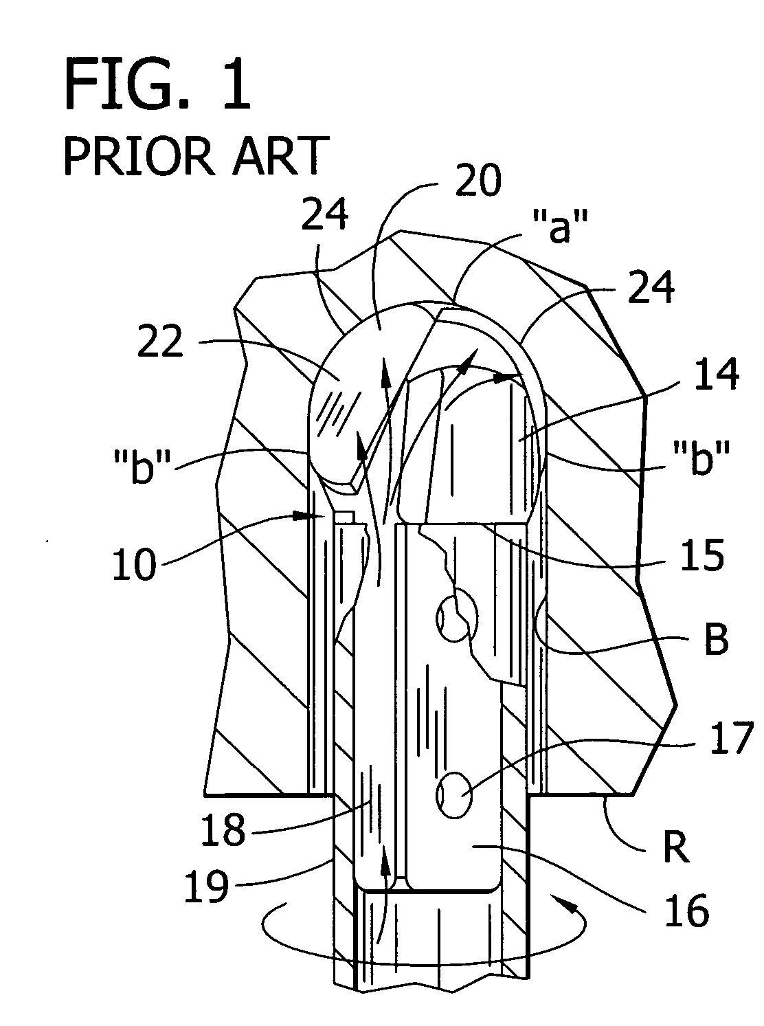
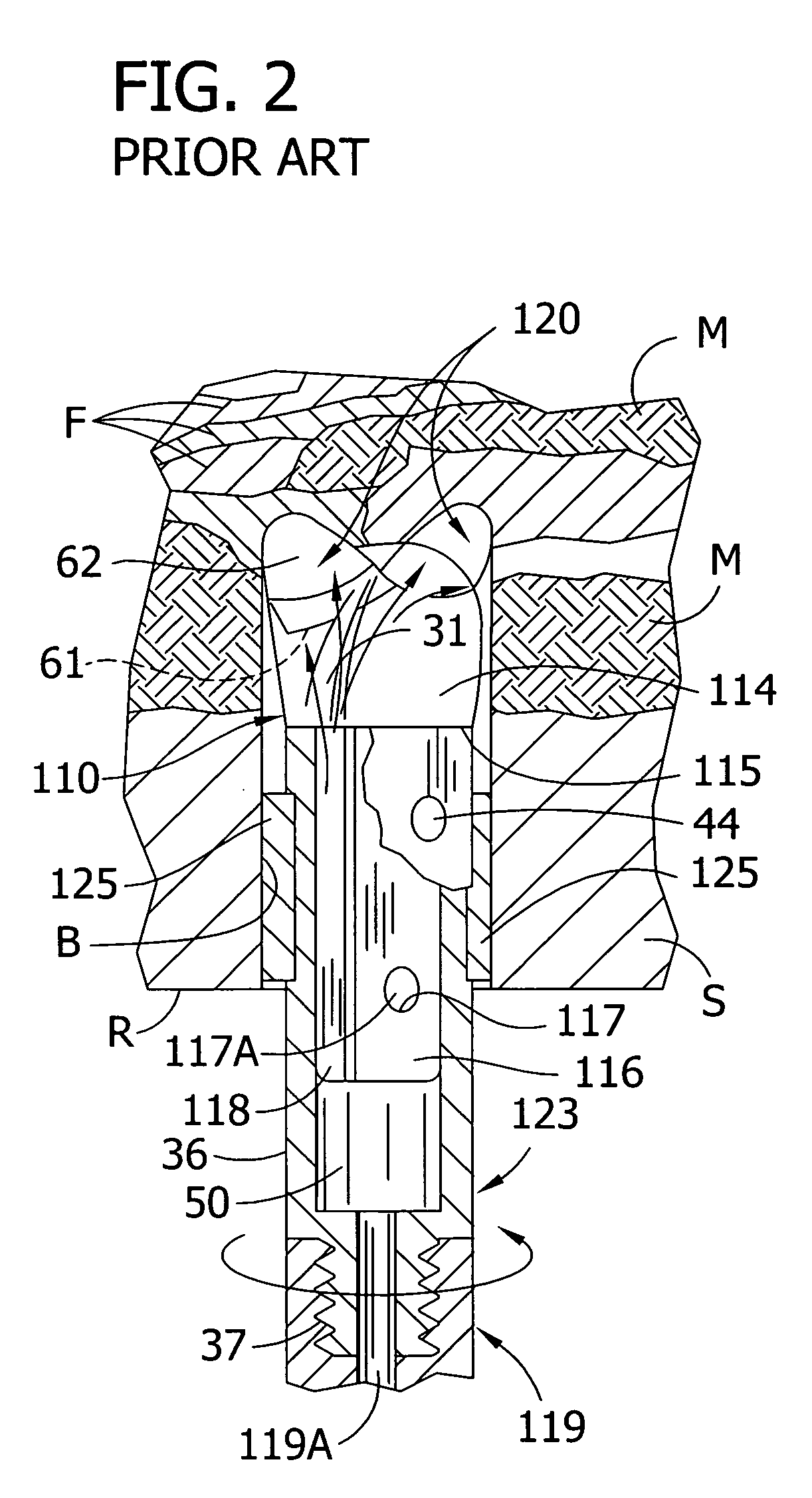
[0024] The present invention relates to improvements in rotary drag bits, particularly roof drill bits for boring and drilling operations in metal / non-metal mining and construction, and to methods for carrying out such metal / non-metal mining operations. The following definitions will be useful for a fuller understanding of the scope of the invention disclosed:

[0025]“Metal / non-metal mine” or “metal / non-metal mining” is used herein as a generic or comprehensive term to mean any type of underground mine or tunnel and encompasses ore mining, hard rock mining and coal mining operations.

[0026]“High-fatigue resistant” and / or “high alloy” are used herein with reference to the material strength of steel having a tensile strength in the range of 209,000 to 211,000 psi (typically 209,500 to 210,000 for 4340 steel) and a fatigue yield strength in the range of 135,000 to 145,000 psi (typically 141,000 psi for 4340 steel).

[0027]“Hard / soft rock” is used to designate earth formations that are ex...


PUM

PropertyMeasurementUnit
diameteraaaaaaaaaa
tensile strengthaaaaaaaaaa

Abstract

The invention is embodied in a heavy duty drill bit for hard / soft rock drilling comprising a high fatigue resistant, high alloy steel bit body having a PCD cutter element of super hard material and an enlarged shank portion constructed to accommodate torsional forces at high thrust pressures, and reamer means for compensating the effect of bore hole rifling. The invention further involves the method of forming a roof bolting matrix in extremely hard rock formations having a compression strength up to about 50,000 psi using PCD wafers on a high tensile strength steel body coupled by a heavy duty shank through high fatigue resistant reamer means to a high strength drive steel member.

Description

BACKGROUND OF THE INVENTION [0001] 1. Field of the Invention [0002] The invention relates generally to improvements in roof drilling systems used in the industry, mining and construction fields. [0003] 2. Description of the Prior Art [0004] Polycrystalline diamond (PCD) has become widely used in making cutting tool inserts. PCD materials are formed of fine diamond powder sintered by intercrystalline synthesis technology into a predetermined layer or shape; and such PCD layers are usually bonded to a substrate of “precemented” tungsten carbide to form a polycrystalline diamond compact (PDC) or insert (e.g. cutting element). The term “high density ceramic” (HDC) is sometimes used to refer to a mining tool having an insert with a PCD layer. The term “chemical vapor deposition” (CVD) is a form of pure PCD used for inserts, and “thermally stable product” (TSP) is another form of pure diamond that can be bonded to a carbide substrate or directly to a steel bit body using new vacuum furnac...

Claims


Application Information

Patent Timeline
Patent Type & Authority Applications(United States)
IPC IPC(8): E21B7/00
CPCE21B10/26E21B10/62
Inventor BRADY, WILLIAM J.
Owner WILLIAM J BRADY LOVING TRUST THE
Why Eureka
Try Eureka